
Multi-phase dc-dc power converter

a power converter and multi-phase technology, applied in the direction of dc-dc conversion, power conversion systems, instruments, etc., can solve the problems of negative influence on the output voltage of the cot regulator and power conversion efficiency, increase of output ripple, and inability to meet the requirements of dc-dc conversion efficiency,

Active Publication Date: 2013-02-14
UPI SEMICON CORP
View PDF6 Cites 30 Cited by
  • Summary
  • Abstract
  • Description
  • Claims
  • Application Information

AI Technical Summary

Benefits of technology

The invention is about a multi-phase DC-DC power converter that uses a feedback circuit, a ramp generator, a PWM generator, and a phase channel current sensor to control the output voltage. This converter has multiple output stage circuits that provide a more uniform current output and better efficiency in terms of current utilization. The PWM controller generates a PWM signal with a constant on time and adjusts its duty cycle based on the input voltage, output voltage, and ramp signal. The ramp generator generates a complete sawtooth wave with fixed rising and falling slopes to enhance the accuracy of the control. The feedback circuit senses the output current and outputs a trigger signal, which is used by the PWM controller to control the output stage circuits and adjust the duty cycle of the PWM signal. This multi-phase DC-DC power converter provides a more stable and efficient output voltage, especially for applications with high load current requirements.

Problems solved by technology

However, in the COT regulator, although the high ESR can provide the regulated output voltage, it probably causes increase of an output ripple, which may have a negative influence on the output voltage of the COT regulator and power conversion efficiency.
Therefore, the conventional method is limited according to an actual phase separation of different channels.

Method used


Image

  • Multi-phase dc-dc power converter
  • Multi-phase dc-dc power converter
  • Multi-phase dc-dc power converter

Examples


Embodiment Construction

[0016]In order to make the aforementioned and other features and advantages of the invention comprehensible, several exemplary embodiments accompanied with figures are described in detail below.

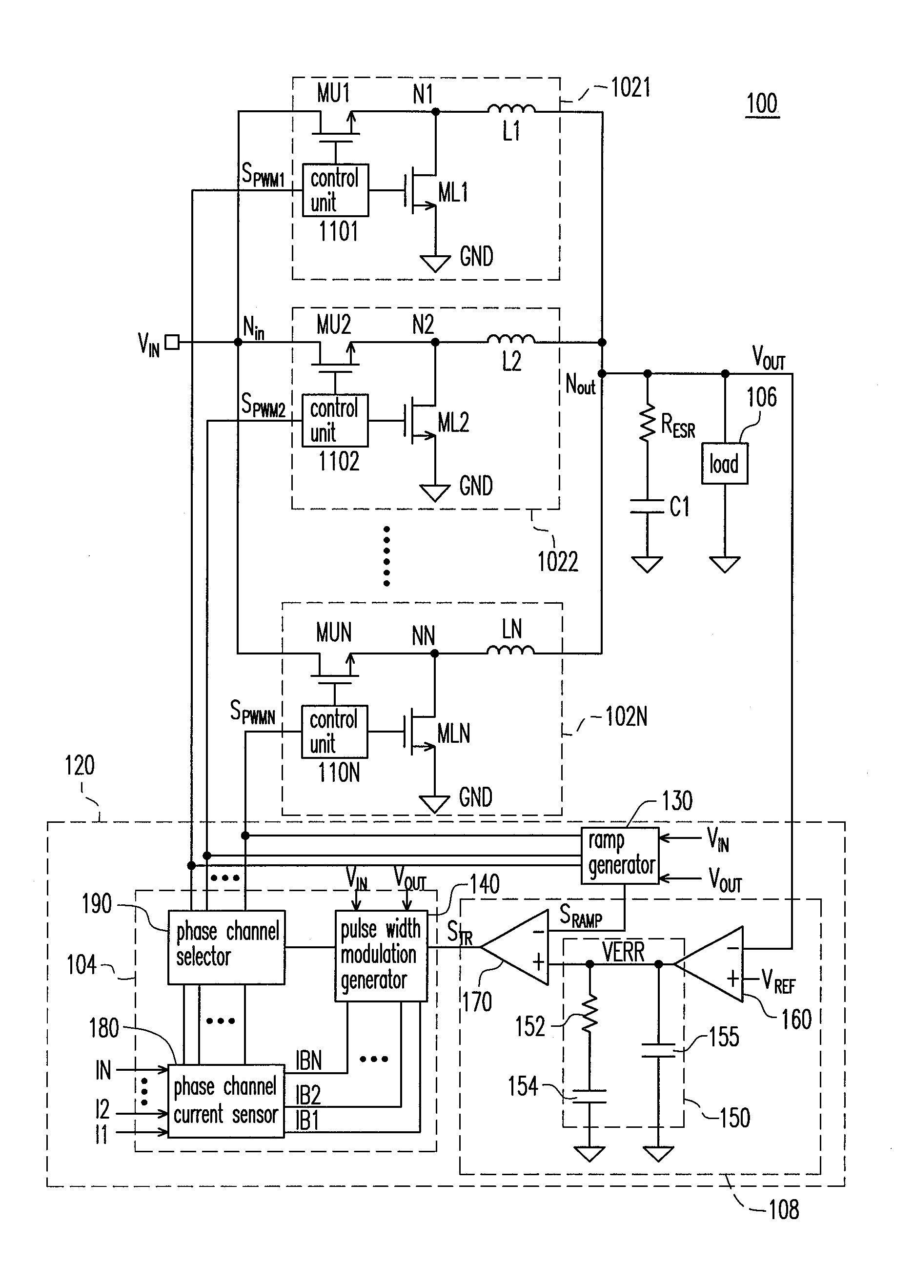
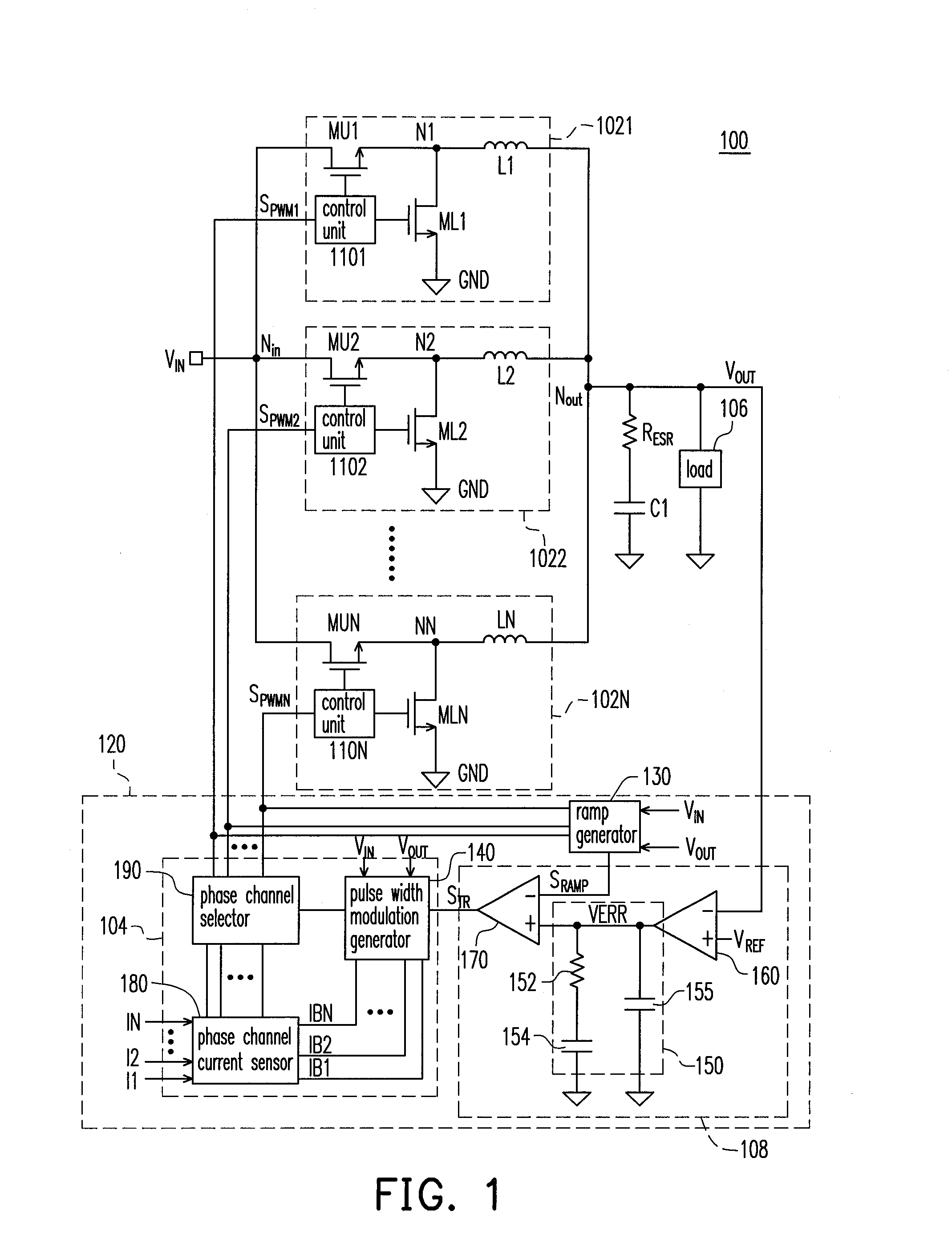
[0017]FIG. 1 is a schematic diagram of a multi-phase DC-DC power converter 100 according to an embodiment of the invention. The multi-phase DC-DC power converter 100 includes a plurality of output stage circuits 1021-102N, a pulse width modulation (PWM) controller 120, a resistor RESR, an output capacitor C1 and a load 106, wherein N is a positive integer.

[0018]The output stage circuits 1021-102N are connected in parallel between an input node Nin, and an output node Nout for converting an input voltage VIN received by the input node Nin into an output voltage VOUT, and outputting the output voltage VOUT through the output node Nout. The PWM controller 120 is coupled to input terminals and output terminals (i.e. the output node Nout) of the output stage circuits 1021-102N, and outputs a PWM s...


PUM


Abstract

A multi-phase DC-DC power converter including a pulse width modulation (PWM) controller and a plurality of output stage circuits is provided. The output stage circuits convert an input voltage into an output voltage. The PWM controller includes a PWM generation module, a ramp generator and a feedback circuit. The feedback circuit generates a trigger signal according to the output voltage and a ramp signal. The PWM generation module generates a PWM signal with a constant on time, and adjusts a duty cycle of the PWM signal according to the trigger signal, the input and output voltages, so as to control phase channels of the multi-phase DC-DC power converter in order.

Description

CROSS-REFERENCE TO RELATED APPLICATION[0001]This application claims the priority benefit of Taiwan application Ser. No. 100128940, filed on Aug. 12, 2011. The entirety of the above-mentioned patent application is hereby incorporated by reference herein and made a part of this specification.BACKGROUND OF THE INVENTION[0002]1. Field of the Invention[0003]The invention relates to a multi-phase direct current (DC)-DC power converter. Particularly, the invention relates to a multi-phase DC-DC power converter including a pulse width modulation (PWM) controller with a constant on time (COT).[0004]2. Description of Related Art[0005]Multi-phase DC-DC power converters are applied in different electronic device. A constant on time (COT) regulator is a technique applied in the power converters. Generally, when a feedback voltage is smaller than a reference voltage, the COT regulator can turn on a main switch in a fixed period, and can adjust a turning off time of the main switch to provide a re...

Claims


Application Information

Patent Timeline
Patent Type & Authority Applications(United States)
IPC IPC(8): G05F1/46
CPCH02M2003/1586H02M3/1584H02M3/1586
Inventor WANG, HAN-PANG
Owner UPI SEMICON CORP
Learn More