
Retractable awning

a technology of awnings and awnings, which is applied in the field of retractable awnings, can solve the problems of reducing the service life of awnings, so as to increase the need for tension, increase the transverse tension, and increase the screen tension

Inactive Publication Date: 2013-02-14
CUTLER
View PDF7 Cites 13 Cited by
  • Summary
  • Abstract
  • Description
  • Claims
  • Application Information

AI Technical Summary

Benefits of technology

The patent describes a covering apparatus for a screen that can be extended and retracted. The motors that control the screen are coordinated to prevent sagging of the screen during extension and retraction. The tension in the screen can be monitored using a tension meter, which is connected to the end supports or the tensile wire. The tension in the screen is controlled by adjusting the speed of the motors to compensate for any discrepancies. The position of the screen can also be monitored using optical distance measuring or rotary encoders. A transverse difference in height between the end points of the screen can be introduced to increase tension in the screen during extension and retraction. This helps to prevent sagging of the screen and allows for better drainage of water.

Problems solved by technology

A major problem with all of these types of covering is providing sufficient tension in the screen so that the canopy does not sway unduly or flap in the wind.
However, the limit of tension which can be provided by springs is fairly low and varies with the length of the screen which has been extended.
Also, springs lose their elasticity over time or if they are extended too far.
This limit of tension has been a major factor in limiting the size (both width and length) of such covering systems.
Thus tension can be readily applied to the screen, and is limited only by the strength of the clamping system, the wires and the screen itself as opposed to springs as in the prior art.
However, the clamping systems will be subject to external forces such as wind, and other obstacles to movement such as debris on the tensile wires.
Furthermore, the clamping systems can slip along wires (e.g. if they are wet or greasy), again, in a non-equal fashion.
Also the motors may provide different drive forces, for example due to manufacturing tolerances or, variations in the power supply may cause one motor to pull momentarily stronger or to suffer a lull.
This can cause unbalanced pulling forces to be applied to the screen which can consequently be deployed and retracted in a lopsided fashion.
Not only does this make the screen less effective, but it can damage the screen.
These drawbacks will be particularly pronounced with larger screens where the clamping units have to travel greater distances and support heavier weights.
Where a large canopy is involved, a significant retraction force is required which can be difficult to provide.
When retracting the screen with unbalanced forces at either side of the screen, there is a further problem; with the unequal forces, the screen can become skewed and as it is retracted onto the storage roller, the screen may not roll up straight.
Also uneven pulling can lead to wrinkles forming in the screen.
As these wrinkles are wound onto the screen, they become folds and creases in the fabric.
Such wrinkles and creases create weaknesses in the fabric of the screen.
Under the high tensions involved in such canopies, there is a greatly increased chance of the fabric tearing at such weaknesses.
Once the screen has been deployed, even when the clamps are clamped in place, external forces such as wind can still cause them to move, thus resulting in a loss in tension or an uneven tension in the screen.
As the screen is raised significantly above the ground, wind passes both over and underneath the screen and the screen can easily catch the wind and experience high forces.

Method used


Image

  • Retractable awning
  • Retractable awning
  • Retractable awning

Examples


first embodiment

[0106]Further embodiments of the invention will now be described with reference to FIGS. 11, 12 and 13. Many elements of these further embodiments are the same as those of the first embodiment described above and will therefore not be described further.

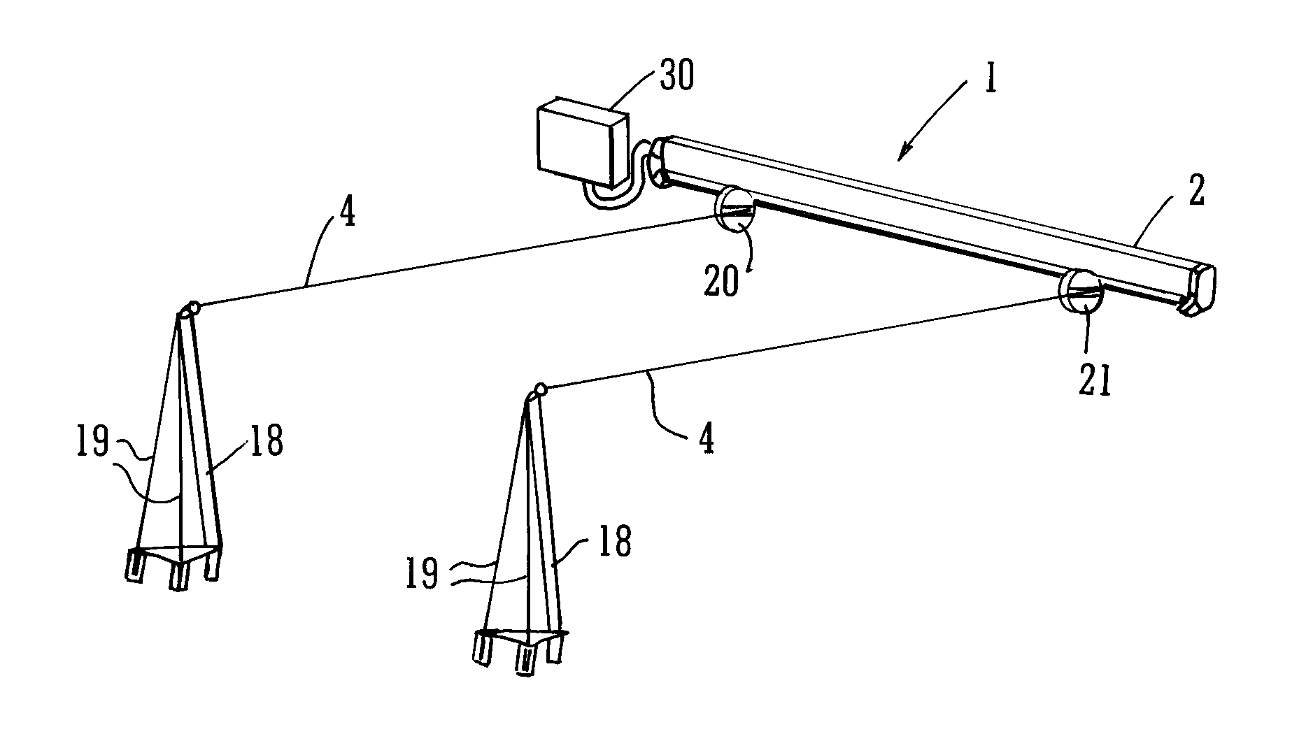
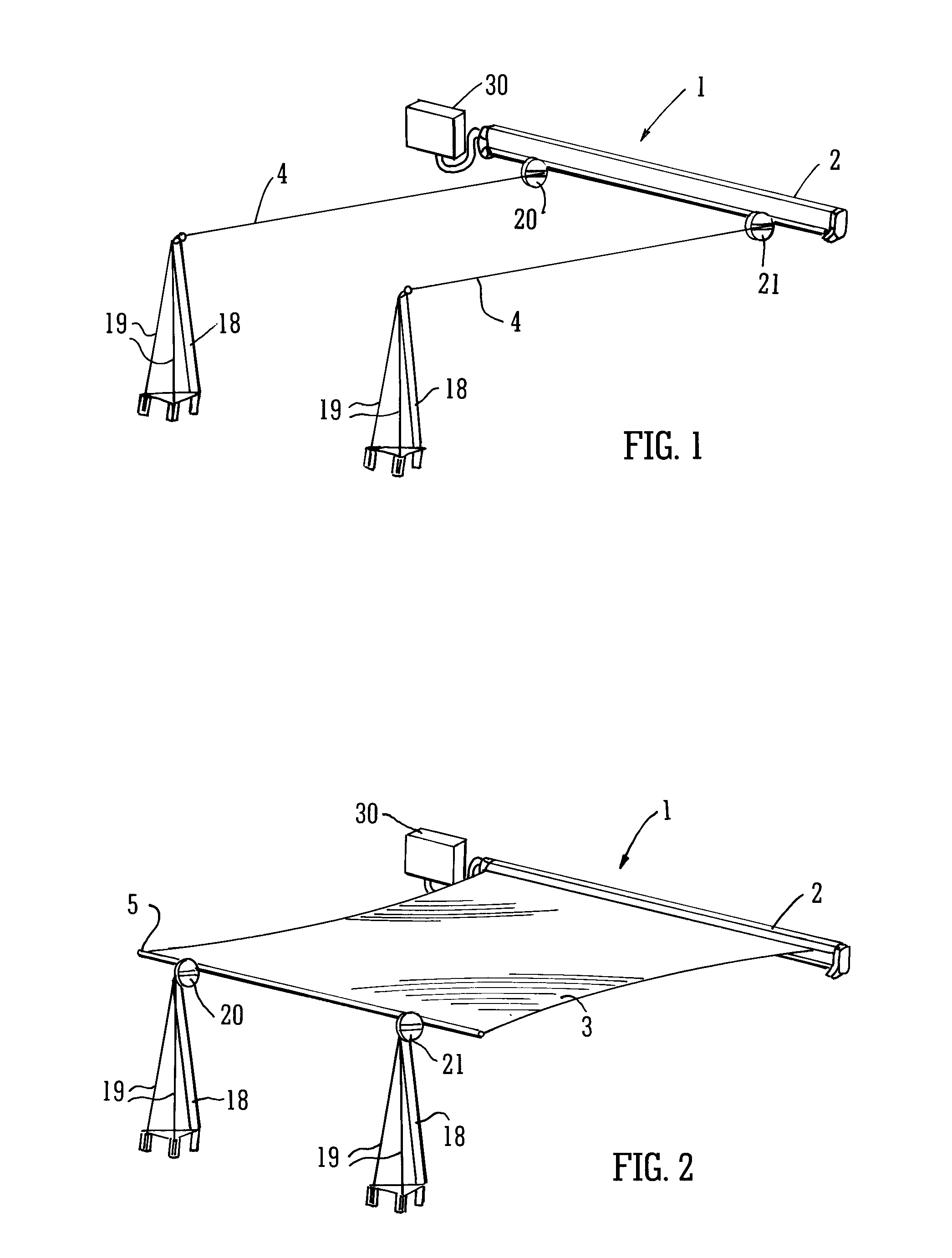
[0107]FIG. 11 shows a second embodiment of the invention. In this embodiment the screen 3 is not deployed and retracted along fixed parallel cables 4 as in the first embodiment, but instead the cables 4 are attached at one end to the corners of the front (leading edge) of the screen 3 and at the other end are attached to winches 200. In the embodiment shown in FIG. 11, the winches 200 are located at ground level and the cables 4 are routed from the top of the support poles 18 through the inside of the poles to the bottom where they exit the poles 18 and are connected to the winches 200. Other arrangements will work equally well. The poles 18 are angled slightly from the vertical and away from the rest of the canopy (in the direction i...

fourth embodiment

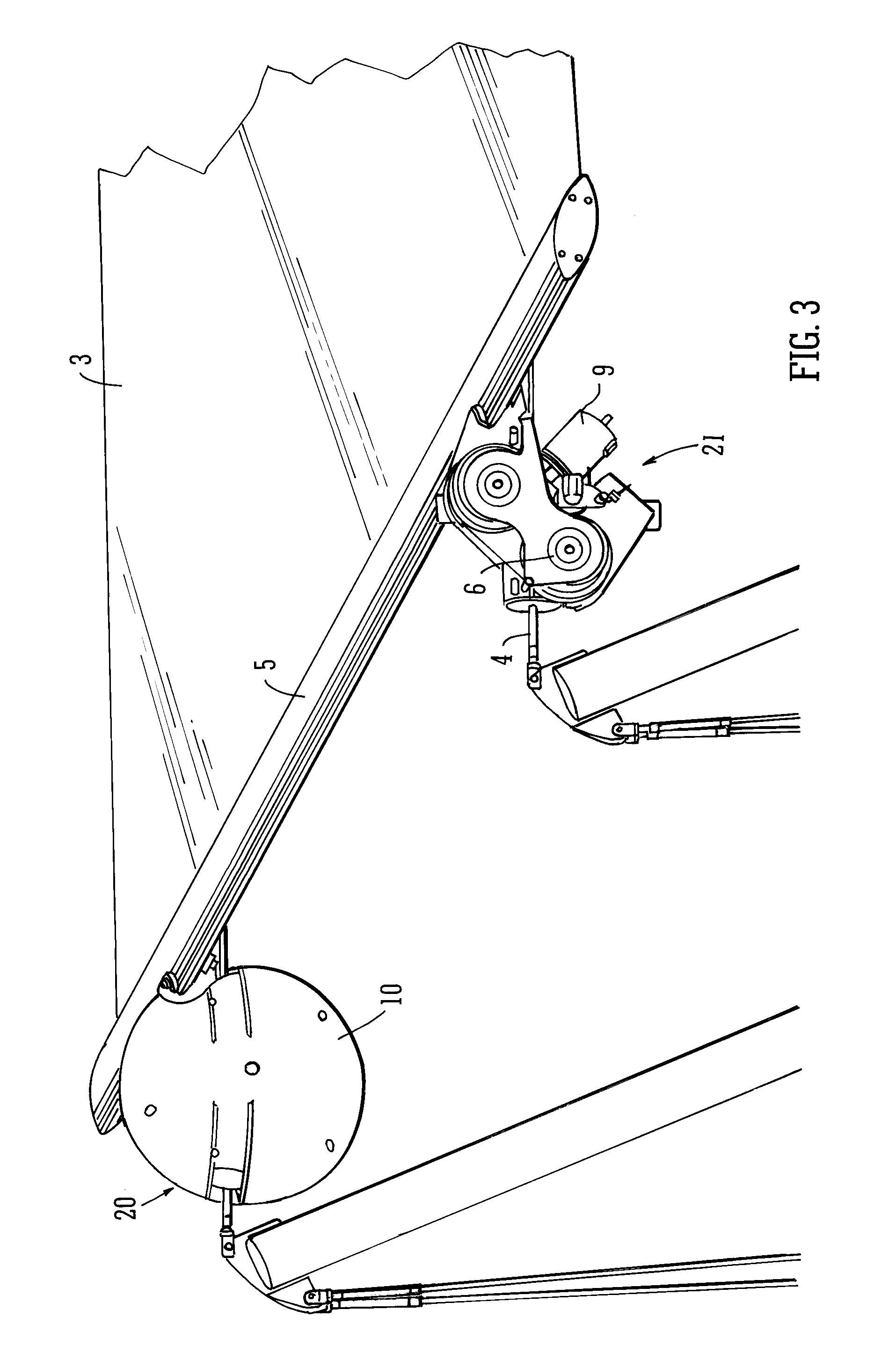
[0112]FIG. 13 shows the invention. This embodiment is similar to the first embodiment of the invention in that the screen 3 is drawn out along fixed cables 4 by means of motor-driven roller units 210 attached to those cables 4. However, in this arrangement, the cables 4 are splayed apart in the direction of extension of the screen 3 by placing the support poles 18 at the front (extension) end of the awning further apart than the attachment points of the cables 4 at the rear (retraction) end of the awning. As in the second and third embodiments, this splaying of the cables 4 creates transverse tension as well as longitudinal tension in the screen 3. The screen 3 is attached to the roller units 210 by means of short connecting wires or rods 215 so as to accommodate the changing angle (and thus the changing transverse tension) as the screen 3 is deployed. Although no tension sensor is shown in FIG. 13, a tension sensor could easily be incorporated into the connecting wires 215 or into ...


PUM


Abstract

A retractable awning. The retractable awning may include a screen that may be extended and retracted, a first motor arranged to extend the screen, a second motor arranged to retract the screen, and a control unit arranged to control the first motors and the second motor.

Description

RELATED APPLICATIONS[0001]The present application is a continuation of U.S. patent application Ser. No. 12 / 525,684, filed in the United States on Aug. 4, 2009, now allowed. U.S. patent application Ser. No. 12 / 525,684 is incorporated by reference herein in full.TECHNICAL FIELD[0002]The present invention relates to a retractable covering apparatus such as a canopy or awning, having a control unit for controlling the extension and retraction thereof. The invention also extends to a control system for such an apparatus, and a method for operating a covering apparatus.BACKGROUND OF THE INVENTION[0003]Awnings or canopies are often used for example outside restaurants or in private gardens to cover open areas and provide shelter for the people underneath them, thereby providing sun protection, rain protection or the like. A variety of covering apparatuses are known in the art. For example some canopies are provided on the side of a building, with folding arms which can be extended out from...

Claims


Application Information

Patent Timeline
Patent Type & Authority Applications(United States)
IPC IPC(8): E04F10/06E04F10/00E04H15/58
CPCA01G9/227E04F10/0681E04F10/0644E04F10/0607Y02A40/25A63C19/12E04F10/06A01G9/22
Inventor CUTLER
Owner CUTLER
Learn More