
Real-time network node location system and method

a node location and real-time network technology, applied in the field of wireless local area networks, can solve the problems of inability to take into account multi-path effects or signal propagation differences, prohibitively complicated and expensive, and omni-directional rssi-based systems do not solve the problem

Inactive Publication Date: 2013-01-31
BUZBY NETWORKS
View PDF7 Cites 15 Cited by
  • Summary
  • Abstract
  • Description
  • Claims
  • Application Information

AI Technical Summary

Benefits of technology

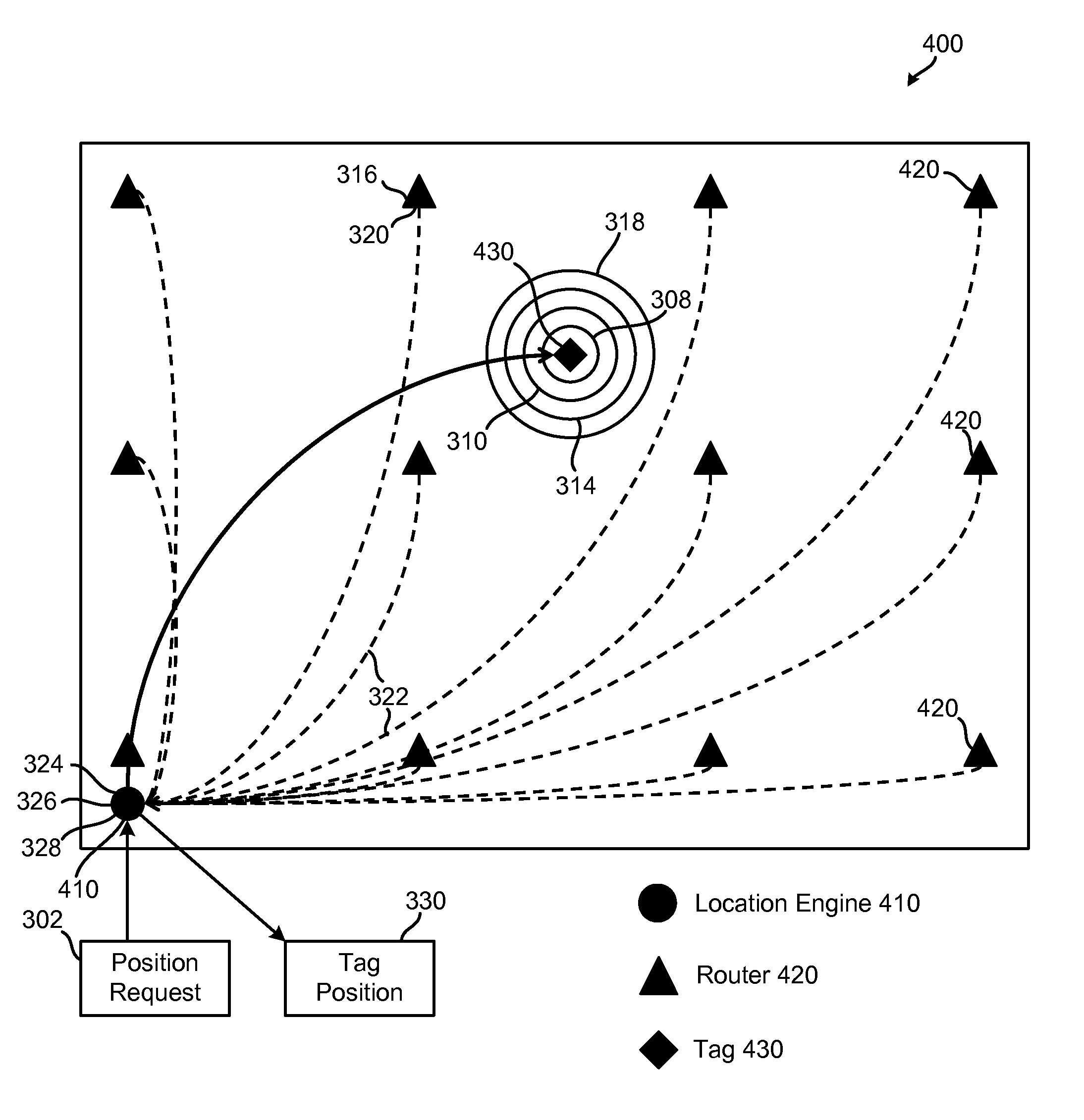
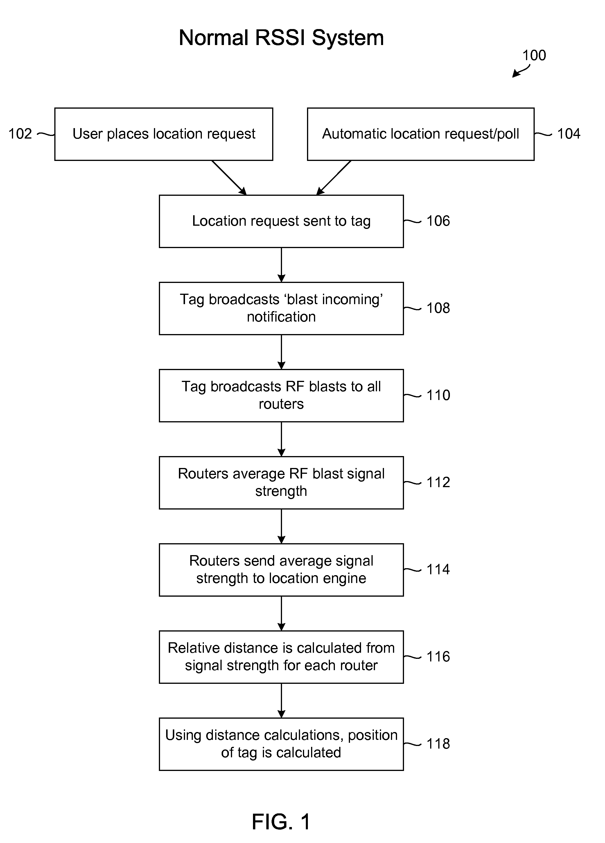
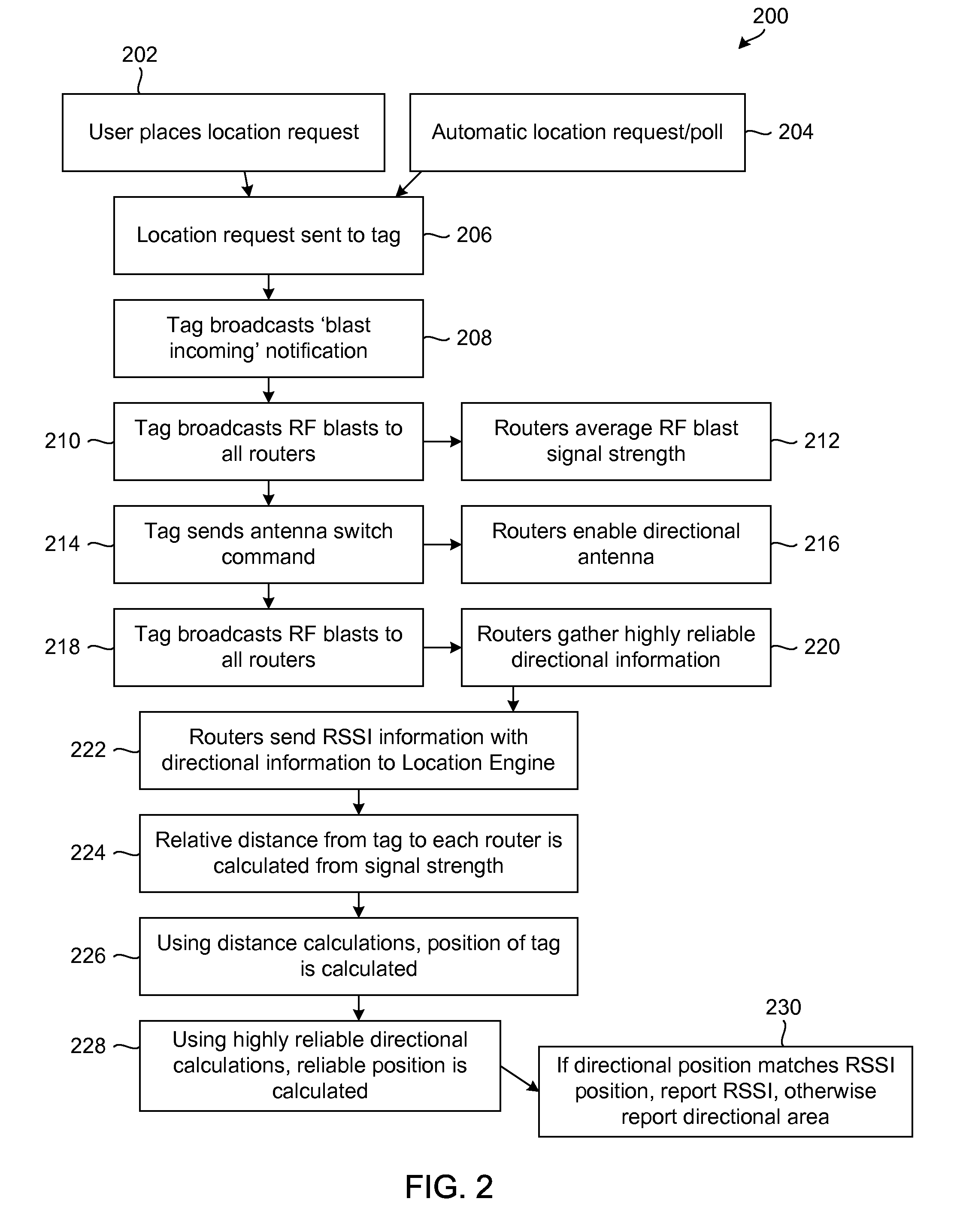
The invention relates to a system and method for real-time location tracking of a tag using a network of routers and a location engine. The system includes a tag that broadcasts multiple signals to nearby routers, which then use omni-directional and directional antennas to receive the signals. The routers then transmit the information about the signal strengths to the location engine. The engine processed the information to determine the position and area of the tag. The technical effect of this invention is the ability to accurately track the position and area of a tag in real-time, which can be useful in various applications such as sports arenas and retail stores.

Problems solved by technology

However, this system does not take into account multi-path effects or signal propagation differences.
Additionally, ToF measurements typically require synchronous clock signals on all devices making them prohibitively complicated and expensive.
However, omni-directional RSSI-based systems do not solve the problem of multipath effects or singularities that arise from these multipath effects.
AoA systems are currently too expensive due to the signal processing power needed to recognize small differences in phase.
The patent application 2008 / 0130604 recognizes the problem that exists with just one of these technologies, but this idea does not address the expense of synchronized clocks that are needed in the ToFA measurements.

Method used


Image

  • Real-time network node location system and method
  • Real-time network node location system and method
  • Real-time network node location system and method

Examples


Embodiment Construction

[0030]The present invention will now be described with reference to the accompanying figures. It is to be understood that the specific systems, methods, and apparatuses illustrated in the attached figures and described in the following specification are simply exemplary embodiments of the present invention and are not to be considered as limiting.

[0031]The system of the present invention, in an embodiment, utilizes the potential accuracy of an RSSI-based positional location finding system with the reliability of a system that provides sector or other area locating. The RSSI data may be collected using router omni-directional (360°) antennas, while the sector or other area forming data may be collected by router antennas that provide a limited directional response. The limited responses of these antennas may create a sector-based or other area-based system that can be used to check the results of the position-finding RSSI system. In an embodiment, the area locating system may also be...


PUM


Abstract

A system for determining a position of location of a tag includes, in an embodiment: a plurality of routers each including at least one antenna; and a location engine to: (a) determine for at least one router, from signals sent by the one router and at least part of which are received by the at least one antenna of each of at least one other of the routers, an average path loss of signal strength; (b) optimize, for at least the one router, multipath parameters in a radio-frequency signal propagation equation using the average path loss for each of the at least one other of the routers and known distance between the router and each of the at least one other of the routers; and (c) determine the position of location of the tag using at least the optimized multipath parameters.

Description

CROSS-REFERENCE TO RELATED APPLICATIONS[0001]The present application is a continuation of U.S. patent application Ser. No. 12 / 728,966, filed Mar. 22, 2010, which is incorporated herein by reference.BACKGROUND OF THE INVENTION[0002]1. Field of the Invention[0003]The invention relates to the field of wireless local area networks (WLAN), and more particularly, to a wireless system for locating mobile nodes within a monitored environment using a combination of RSSI (received signal-strength indicator) and sector discrimination using an array of limited-field-of-view antennas.[0004]2. Description of Related Art[0005]Wireless area networks are becoming more commonplace as wireless devices decrease in size, cost, and power consumption. As these devices slowly replace their wired counterparts in the areas of sensors and personal wireless devices, networks grow from a few devices to become facility-wide webs, where information really is only a few wireless hops away. The ZigBee wireless prot...

Claims


Application Information

Patent Timeline
Patent Type & Authority Applications(United States)
IPC IPC(8): H04W24/00H04W4/029
CPCG01S5/0252G01S5/12H04W4/028G01S2013/466G01S5/14H04W4/029G01S5/0268
Inventor DAVIDSON, ERIK J.BILEN, SVEN G.WEISS, DANIEL R.PLATT, NICHOLAS E.WEIR, ERIK D.
Owner BUZBY NETWORKS
Learn More