
Mobile terminal and power control method

a technology of power control and mobile terminal, which is applied in the direction of power supply for data processing, instruments, measurement devices, etc., can solve the problems of high frequency of second battery exchange, low battery capacity of the first battery, and power consumption, and achieve the effect of suppressing the consumption of the first battery

Active Publication Date: 2013-01-17
NEC PLATFORMS LTD
View PDF2 Cites 13 Cited by
  • Summary
  • Abstract
  • Description
  • Claims
  • Application Information

AI Technical Summary

Benefits of technology

The patent text describes a power control method for mobile terminals that reduces the battery consumption and frequency of battery exchange when the terminal is not being actively used. This is important for maintaining the functionality of the terminal while reducing the risk of tampering. The method involves turning off the power-supply switch when the network is not being used, and increasing the capacity of the battery or limiting the consumed current of the tamper-detection circuit to extend the life of the battery.

Problems solved by technology

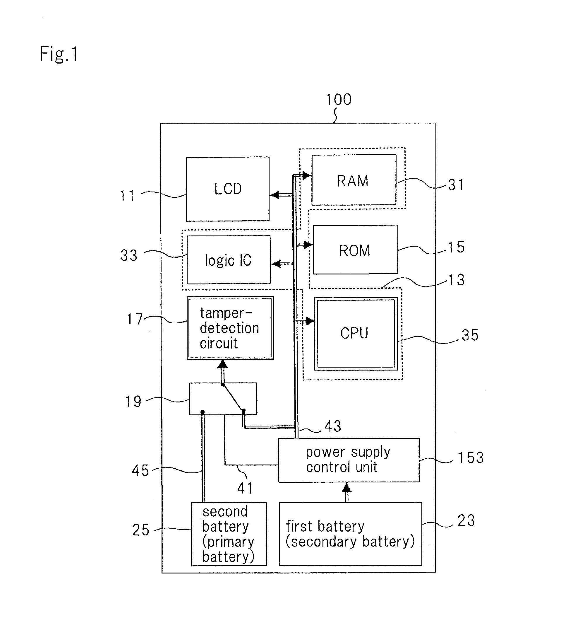
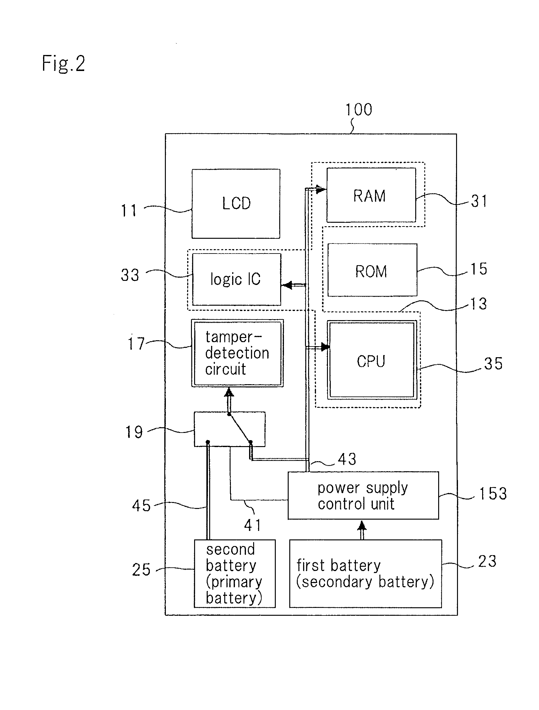
Even while being held in reserve, power is being consumed due to the operation of the suspend function and tamper-detection circuit, and as a result, even though the equipment is not being used in business, the battery capacity of the first battery becomes low in a short time period and the power supply to the tamper-detection circuit switches from the first battery to the second battery at an earlier stage than the manager of terminals may imagine.
The problem therefore arises of the high frequency at which the second battery is exchanged.

Method used


Image

  • Mobile terminal and power control method
  • Mobile terminal and power control method
  • Mobile terminal and power control method

Examples


Embodiment Construction

[0035]The configuration of the mobile terminal of the present exemplary embodiment is next described.

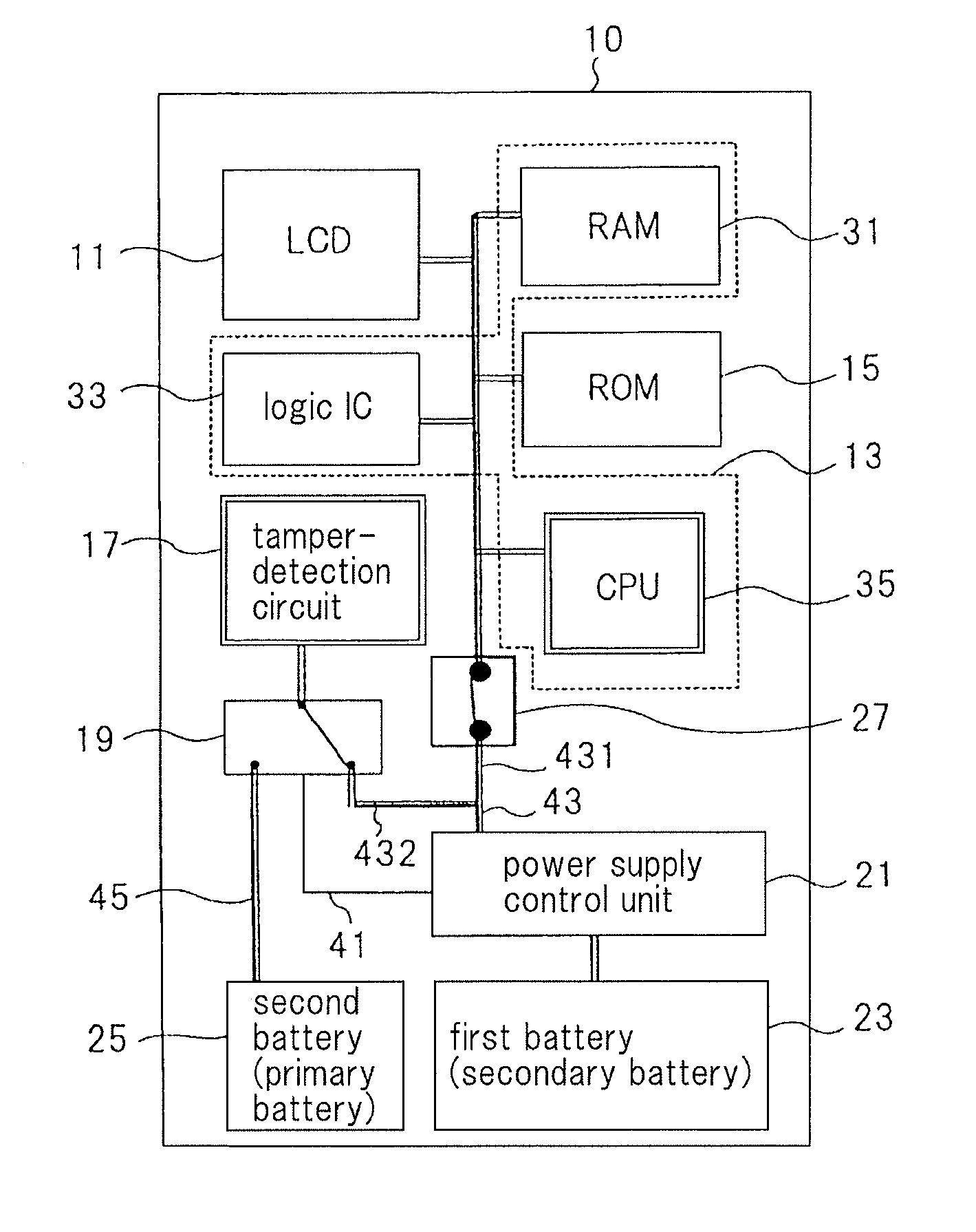
[0036]FIG. 3 is a block diagram showing an example of the configuration of the mobile terminal of the present exemplary embodiment. Constructions that are the same as constructions shown in FIG. 1 are given the same reference numbers and detailed explanation of these constructions is omitted.

[0037]As shown in FIG. 3, mobile terminal 10 of the present exemplary embodiment includes: LCD 11, information processor 13, ROM 15, tamper-detection circuit 17, switch 19, power supply control unit 21 that supplies power to each unit, first battery 23, second battery 25, and DIP switch 27 provided between information processor 13 and power supply control unit 21.

[0038]In the present exemplary embodiment, first battery 23 is assumed to be a “secondary battery” that can be reused by charging. Second battery 25 is assumed to be a “primary battery” that can only be discharged and not be charged. Alt...


PUM


Abstract

A mobile terminal includes: a tamper-detection circuit (17), an information processor (13) that is capable of executing a suspend function, a first battery (23) supplying power to the information processor (13) and the tamper-detection circuit (17), and a switch (27) that is provided on a power-source supply line (431) that connects the first battery (23) and the information processor (13) and the switch that is capable of switching between a state in which information processor (13) is connected to first battery (23) and a state in which information processor (13) is not connected to first battery (23).

Description

TECHNICAL FIELD[0001]The present invention relates to a mobile terminal and a power control method.BACKGROUND ART[0002]Mobile terminals such as mobile POS (Points of Sales) and PDA (Personal Digital Assistants) should be turned off whenever not in use to limit battery consumption as much as possible but are preferably quickly ready for use when necessary. As a result, some mobile terminals have a suspend / resume function (hereinbelow referred to as simply a “suspend function”).[0003]According to the suspend function, when the power-supply switch is turned OFF, the state of the terminal immediately preceding turning OFF the power-supply switch is saved, and when the power-supply switch is subsequently turned ON, the state of the terminal immediately preceding turning OFF the power-supply switch is restored. According to this function, the operator of the mobile terminal, when turning ON the power-supply switch, is able to resume work from the state that immediately preceded turning OF...

Claims


Application Information

Patent Timeline
IPC IPC(8): G06F1/26G06F21/75G06F21/86
CPCG06F1/26G06F1/263G06F1/3203
Inventor SUMIDA, HARUHIKO
Owner NEC PLATFORMS LTD
Learn More