Position detecting sensor and position detector
a technology of position detection and sensor, which is applied in the field of position detection sensors, can solve problems such as complicated configuration of position detectors
- Summary
- Abstract
- Description
- Claims
- Application Information
AI Technical Summary
Benefits of technology
Problems solved by technology
Method used
Image
Examples
first embodiment
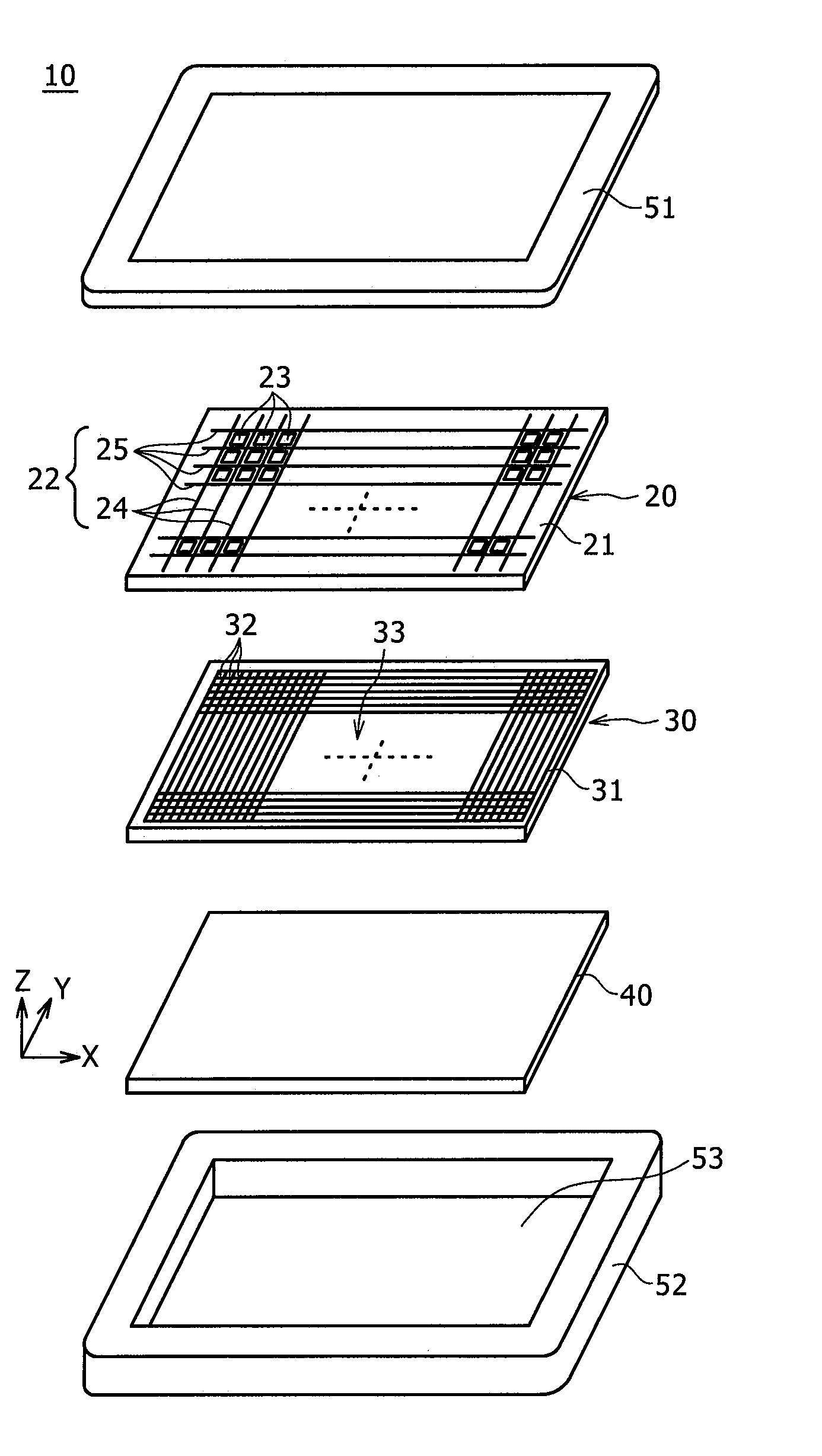
[0047]FIG. 1 is an exploded perspective view showing an example of a position detector including a first embodiment of a position detecting sensor according to the present invention. The example shown in FIG. 1 illustrates a construction of a tablet device, including a position detecting sensor for detecting a position on a display surface of a display device indicated by, for example, a pen (stylus).
[0048]The tablet device 10 of the example, as shown in FIG. 1, is composed of the position detecting sensor 20, a Liquid Crystal Display (LCD) device 30 as an example of the display device, a printed wiring board 40, and an upper case 51 and a lower case 52 that form a chassis of the tablet device 10.
[0049]As shown in FIG. 1, the LCD 30 includes a display surface 33, on which a large number of display pixels 32 are disposed in the X-axis direction (in a transverse or horizontal direction) on an LCD substrate 31, and a large number of display pixels 32 are also disposed in the Y-axis dir...
second embodiment
[0102]When the dummy pattern 23 composed of an ITO film having the same light transmittance as that of each of the first transparent electrodes 24 and the second transparent electrodes 25 is formed in the area, which is surrounded by two adjacent first transparent electrodes 24 and two adjacent second transparent electrodes 25 in the position detecting sensor 20 utilizing the capacitive system, as in the first embodiment described above, a distance “d” between the first transparent electrode 24 and the second transparent electrode 25 is shortened due to the presence of the dummy pattern 23 composed of the conductive member. For this reason, a coupling capacitance C (=k·S / d (k is a proportional constant, and S is a facing area of electrodes)) between the first transparent electrode 24 and the corresponding second transparent electrode 25 becomes large.
[0103]In the cross-point capacitive system, a capacitance change that occurs when the indication body, such as a finger or a position ...
modification examples
of the Second Embodiment
[0121]The second embodiment has been described in such a way that the contours with respect to the Y-axis direction of the plural small dummy patterns 61, 62, 63, and 64 have the inclinations of ±θ in the divided dummy patterns DP. However, it is not necessary, for example, for the two small dummy patterns 61 and 62 disposed in the X-axis direction to have the same parallelogram. As described above, it is only necessary for the divided dummy pattern DP to have a shape corresponding to the shapes of the first transparent electrodes 24 and the second transparent electrodes 25, respectively, so that uniform transmittance can be ensured for the entire position detecting sensor 60. In addition, it is also only necessary to set the inclination angles of the contours of the small dummy patterns 61, 62, 63, and 64 to the determined values, respectively, with respect to the disposition direction of the pixels 32 of the LCD 30 so as to decrease or prevent the generatio...
PUM
 Abstract
Description
Claims
Application Information
 - R&D
- Intellectual Property
- Life Sciences
- Materials
- Tech Scout
- Unparalleled Data Quality
- Higher Quality Content
- 60% Fewer Hallucinations
Browse by: Latest US Patents, China's latest patents, Technical Efficacy Thesaurus, Application Domain, Technology Topic, Popular Technical Reports.
© 2025 PatSnap. All rights reserved.Legal|Privacy policy|Modern Slavery Act Transparency Statement|Sitemap|About US| Contact US: help@patsnap.com


