
Method and Apparatus for Measuring Process Parameters of a Plasma Etch Process

a plasma etching and process parameter technology, applied in the direction of optical radiation measurement, instruments, spectrometry/spectrophotometry/monochromators, etc., can solve the problems of insufficient signal-to-noise ratio, inability to accurately measure the size of workpieces, and high cost of plasma etching reactor integration, etc., to achieve convenient processing and facilitate processing

Inactive Publication Date: 2013-01-17
BULLOCK LARRY +2
View PDF6 Cites 23 Cited by
  • Summary
  • Abstract
  • Description
  • Claims
  • Application Information

AI Technical Summary

Benefits of technology

The present invention is a system, method, and software product for deriving process state parameters from modulated light detected from plasma emissions in a plasma etch process. The system uses a configurable hybrid superheterodyne spectrum analyzer to scan and down-convert the frequency of the modulated light signal. The light signals are then filtered and processed to evaluate plasma parameters and process state information. The system is highly configurable, allowing the controller to alter signal processing parameters for various components on the fly. The technical effects of the invention include improved accuracy in evaluating process states, better understanding of plasma-related phenomena, and improved efficiency in optimizing process parameters.

Problems solved by technology

These methods often include expensive and / or complex integration into plasma etch reactors.
Issues with these method include lack of sufficient signal-to-noise (“S / N”) and sensitivity to workpiece size due to fixed spot sizes.

Method used


Image

  • Method and Apparatus for Measuring Process Parameters of a Plasma Etch Process
  • Method and Apparatus for Measuring Process Parameters of a Plasma Etch Process
  • Method and Apparatus for Measuring Process Parameters of a Plasma Etch Process

Examples


Embodiment Construction

[0030]In the following description, reference is made to the accompanying drawings that form a part hereof, and that show by way of illustration, specific embodiments in which the invention may be practiced. These embodiments are described in sufficient detail to enable those skilled in the art to practice the invention, and it is to be understood that other embodiments may be utilized. It is also to be understood that structural, procedural and system changes may be made without departing from the spirit and scope of the present invention. The following description is, therefore, not to be taken in a limiting sense. For clarity of exposition, like features shown in the accompanying drawings are indicated with like reference numerals and similar features as shown in alternate embodiments in the drawings are indicated with similar reference numerals.

[0031]Prior art systems for monitoring plasma parameters by the detection of modulated light limit the ability to perform multiple desir...


PUM


Abstract

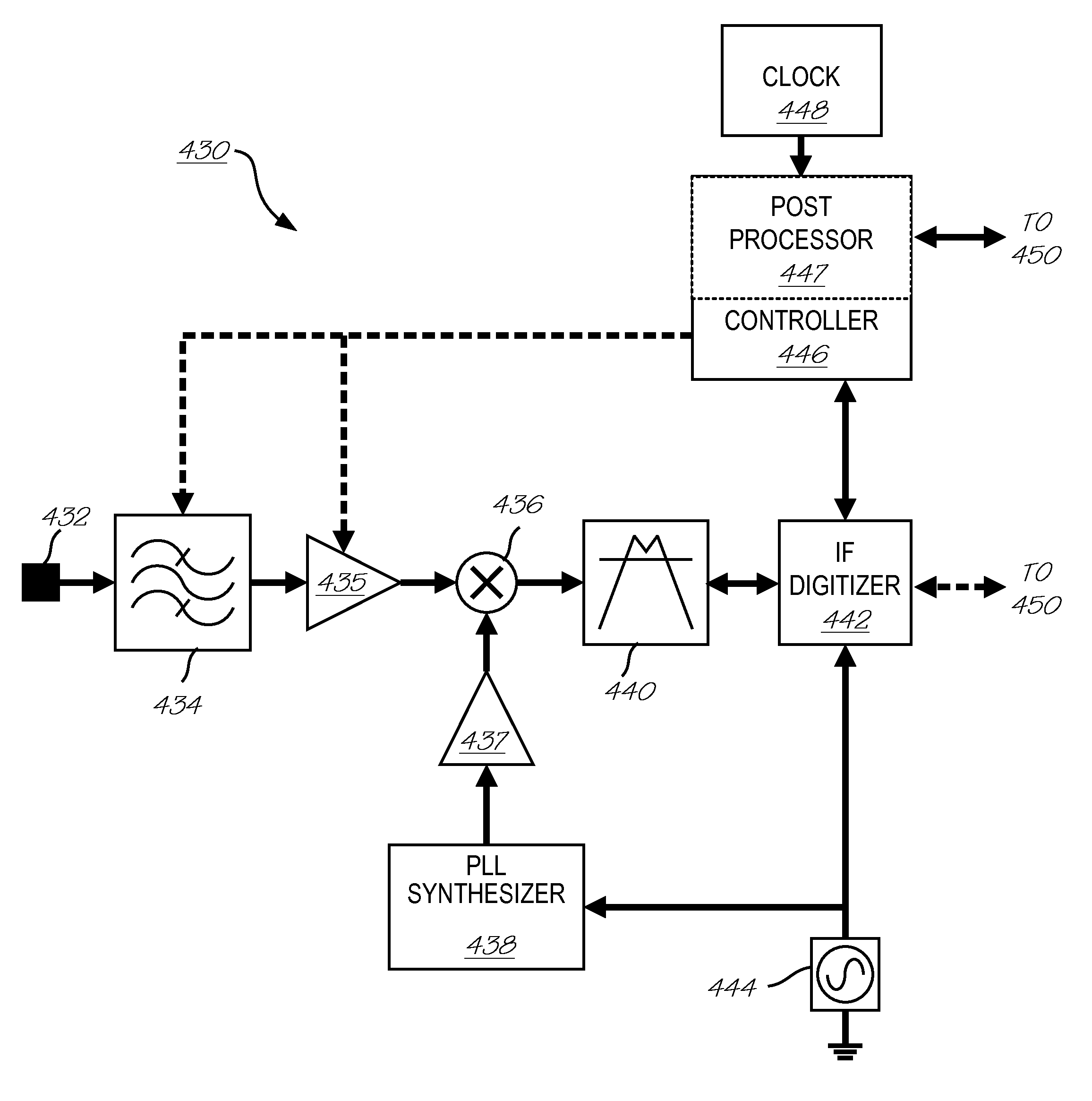
A configurable hybrid superheterodyne spectrum analyzer for deriving process state parameters from detected modulated light emitted by a plasma receives and conditions the electric signals converted from the modulated light for subsequent superheterodyne mixing at a specific intermediate frequency (IF) that is lower than the frequency of the modulated light. Signal conditioning includes filtering noise, aliasing and DC and / or amplifying or de-amplifying the signal. Once mixed, the superheterodyne signal is further filtered by an IF filter to define the signal bandwidth characteristics relevant to the process state parameters. The IF filter may configurably employ multiple filter functions such as Gaussian filtering of increasing widths and / or comb filtering for multiple passbands in the frequency spectrum. Finally, the IF mixed and filtered signal is digitized with respect to the specific intermediate frequency using an IF digitizer. The processed signal is then passed to a signal analyzer for derivation of process state parameters. The system may further include a controller for receiving information from the signal analyzer regarding signal processing requirements and then actively configuring one or all of the signal conditioner filter, signal conditioner amplifier, IF filter and IF digitizer to meet those requirements.

Description

CROSS REFERENCES TO RELATED APPLICATIONS[0001]The present application is related to the following co-pending U.S. patent application: U.S. patent application entitled, “Method and Apparatus for Measuring Process Parameters of a Plasma Etch Process”, having application Ser. No. 12 / 524,855, and with PCT filing date of filed Jan. 31, 2008, currently pending, which is assigned to the assignee of the present invention. The above identified application is incorporated by reference herein in its entirety.BACKGROUND OF THE INVENTION[0002]The present invention relates generally to the monitoring of plasma etch processes. More particularly, the invention relates to a method and an apparatus for determining one or more process parameters of a plasma etching process occurring on a workpiece such as a semiconductor wafer. These process parameters may be indicative of the process state of the workpiece or may be indicative of the process state of the plasma environment or process tool. Process pa...

Claims


Application Information

Patent Timeline
IPC IPC(8): G01J1/34
CPCH01J37/32926H01J37/32972G01J1/4257G01J3/027G01J3/28G01J3/433H01J37/32935G01J3/10
Inventor BULLOCK, LARRYKUENY, ANDREW WEEKSMELONI, MARK ANTHONY
Owner BULLOCK LARRY
Learn More