
Stacked Half-Bridge Power Module

Active Publication Date: 2013-01-17
INFINEON TECH AMERICAS
View PDF8 Cites 54 Cited by
  • Summary
  • Abstract
  • Description
  • Claims
  • Application Information

AI Technical Summary

Benefits of technology

[0009]A stacked half-bridge power module, substantially as shown in and/or described in co

Problems solved by technology

Although the power switch and the diode may be capable of high performance, performance of the power switch and the diode can be limited by how the dies are packaged.
For example, electromagnetic interference (EMI) and parasitics are of great concern when connecting the dies in the power module.
Furthermore, the power devices typically generate significant heat, which can degrade performance of the power switch and the diode if not sufficiently dissipated from the power devices.
However, using this approach, the conductive traces would lik

Method used


Image

  • Stacked Half-Bridge Power Module
  • Stacked Half-Bridge Power Module
  • Stacked Half-Bridge Power Module

Examples


Embodiment Construction

[0014]The present invention is directed to a stacked half-bridge power module. The following description contains specific information pertaining to the implementation of the present invention. One skilled in the art will recognize that the present invention may be implemented in a manner different from that specifically discussed in the present application. Moreover, some of the specific details of the invention are not discussed in order to not obscure the invention. The specific details not described in the present application are within the knowledge of a person of ordinary skill in the art.

[0015]The drawings in the present application and their accompanying detailed description are directed to merely exemplary embodiments of the invention. To maintain brevity, other embodiments of the invention that use the principles of the present invention are not specifically described in the present application and are not specifically illustrated by the present drawings.

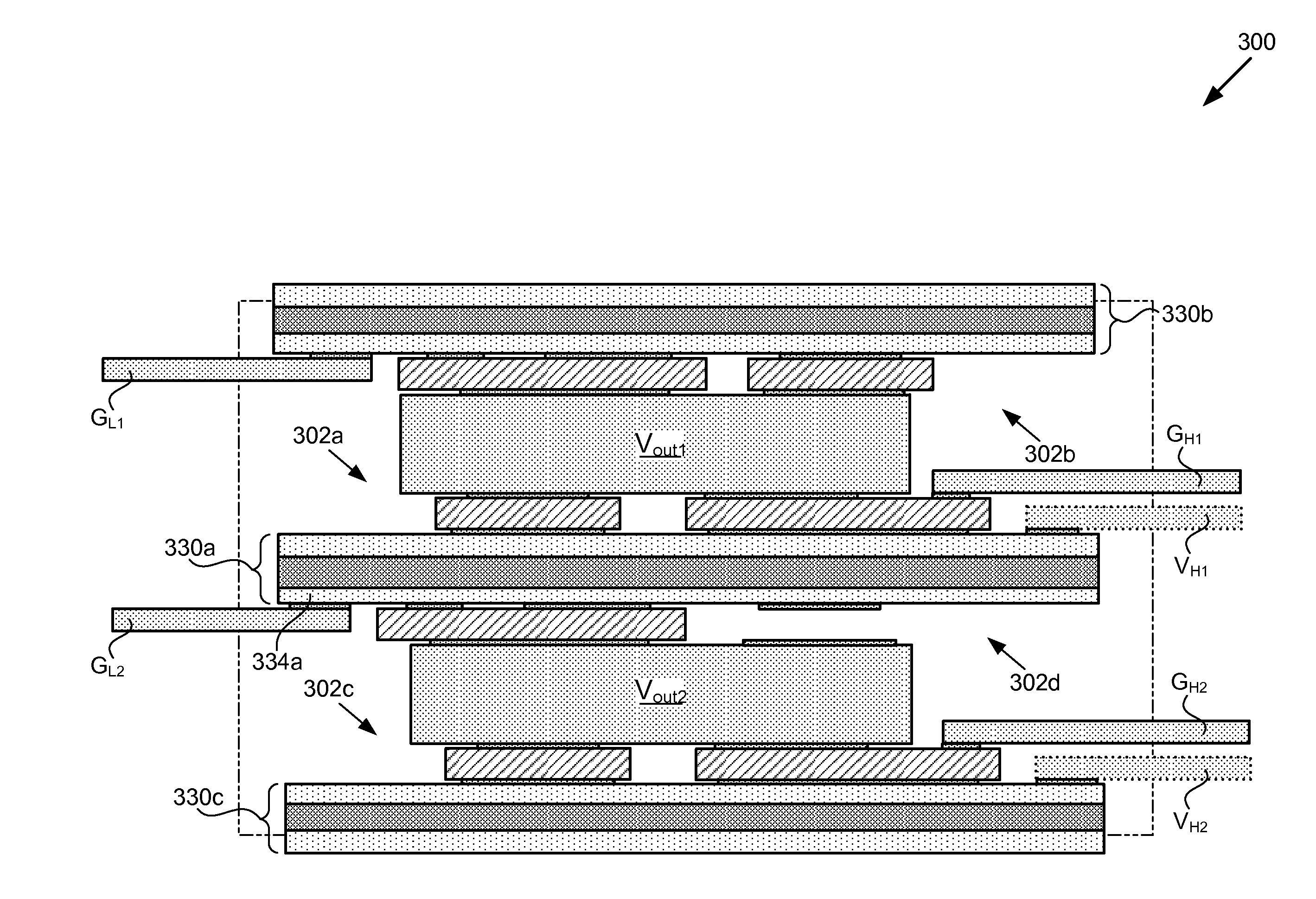
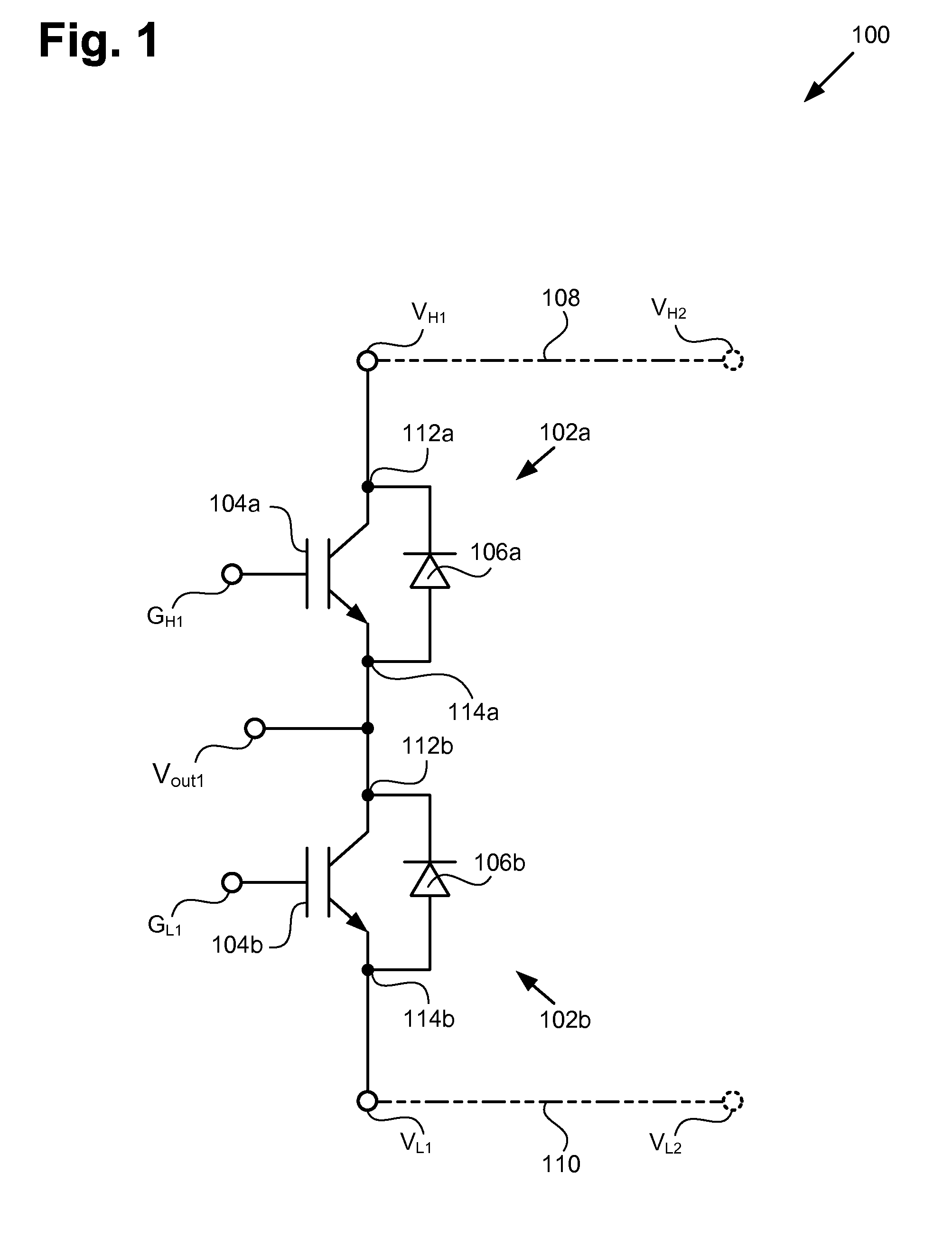
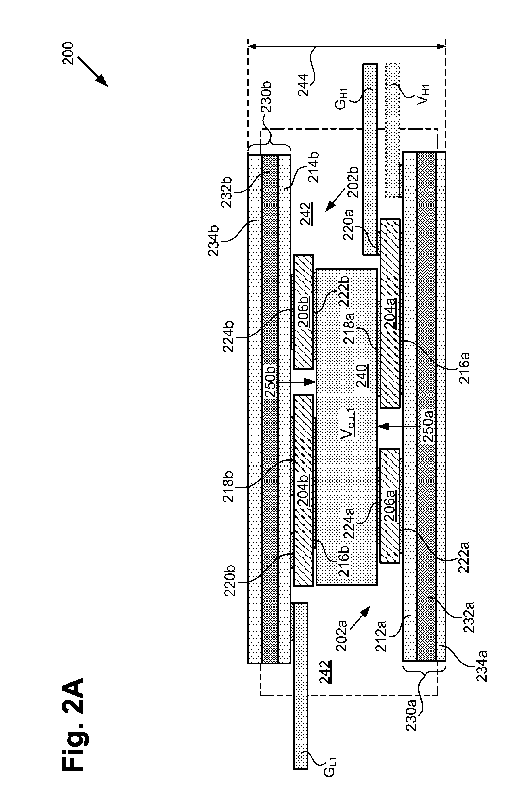
[0016]FIG. 1 shows...


PUM


Abstract

According to an exemplary embodiment, a stacked half-bridge power module includes a high side device having a high side power terminal coupled to a high side substrate and a low side device having a low side power terminal coupled to a low side substrate. The high side and low side devices are stacked on opposite sides of a common conductive interface. The common conductive interface electrically, mechanically, and thermally couples a high side output terminal of the high side device to a low side output terminal of the low side device. The high side device and the low side device can each include an insulated-gate bipolar transistor (IGBT) in parallel with a diode.

Description

[0001]The present application claims the benefit of and priority to a pending provisional application titled “Stacked Half-Bridge Power Module,” Ser. No. 61 / 506,468 filed on Jul. 11, 2011. The disclosure in that pending provisional application is hereby incorporated fully by reference into the present application.BACKGROUND OF THE INVENTION[0002]1. Field of the Invention[0003]The present invention is generally in the field of semiconductors. More particularly, the invention relates to the packaging of semiconductor dies.[0004]2. Background Art[0005]A power module having power devices can be used in high voltage and high current applications. The power module can include a half-bridge where the power devices are high side and low side devices that include, for example, an insulated-gate bipolar transistor (IGBT) or a power metal-oxide-semiconductor field-effect transistor (MOSFET) as a power switch. Each power switch can be provided on a respective die and is commonly in parallel wit...

Claims


Application Information

Patent Timeline
IPC IPC(8): H01L29/739
CPCH01L25/071H01L25/072H01L25/074H05K7/209H01L2924/0002H01L2924/00H01L23/051
Inventor HAUENSTEIN, HENNING M.
Owner INFINEON TECH AMERICAS
Learn More