Use of rotating photovoltaic cells and assemblies for concentrated and non-concentrated solar systems

Inactive Publication Date: 2013-01-10
HOLMES JOHN W +1
View PDF13 Cites 8 Cited by
  • Summary
  • Abstract
  • Description
  • Claims
  • Application Information

AI Technical Summary

Benefits of technology

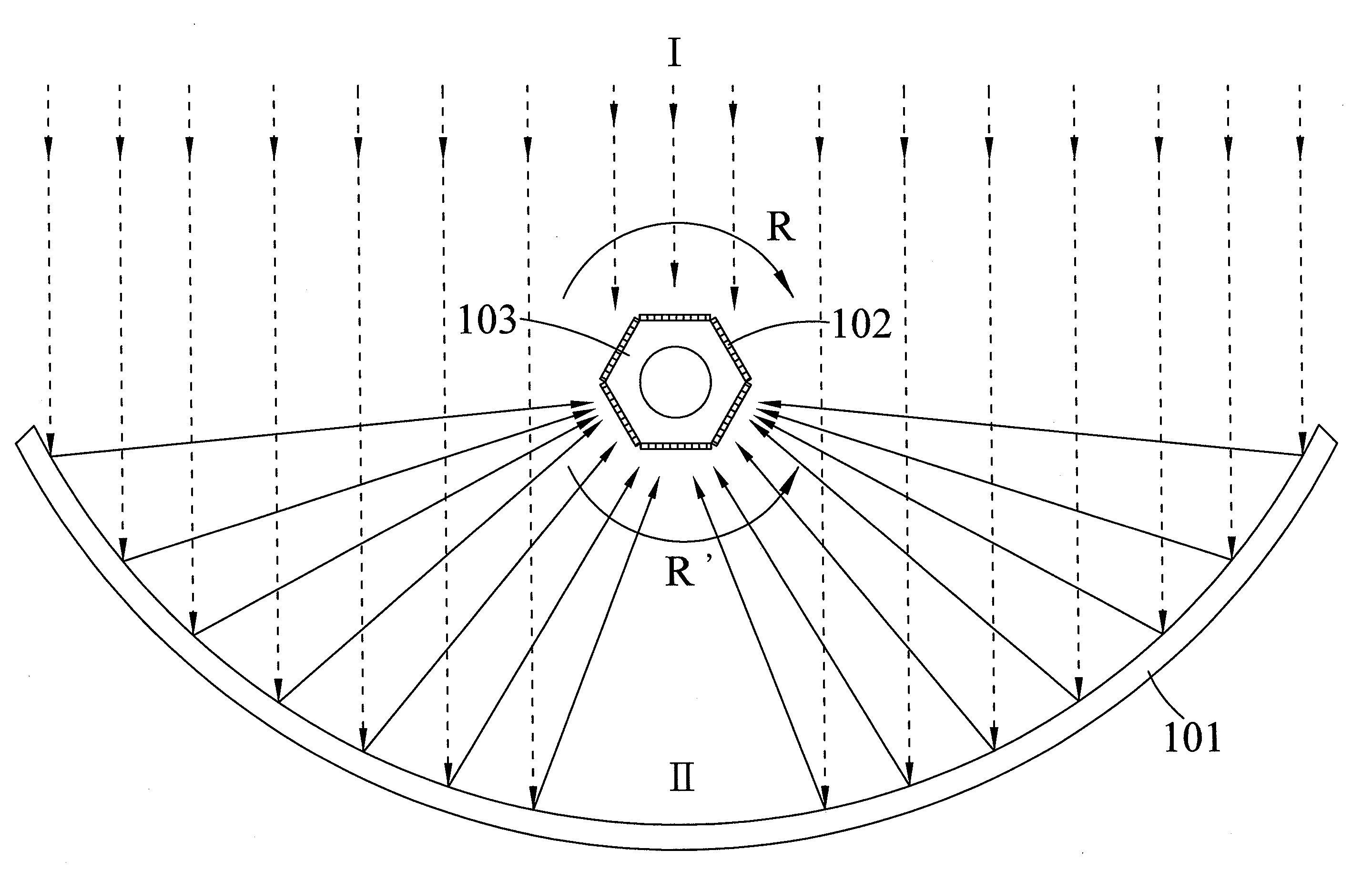
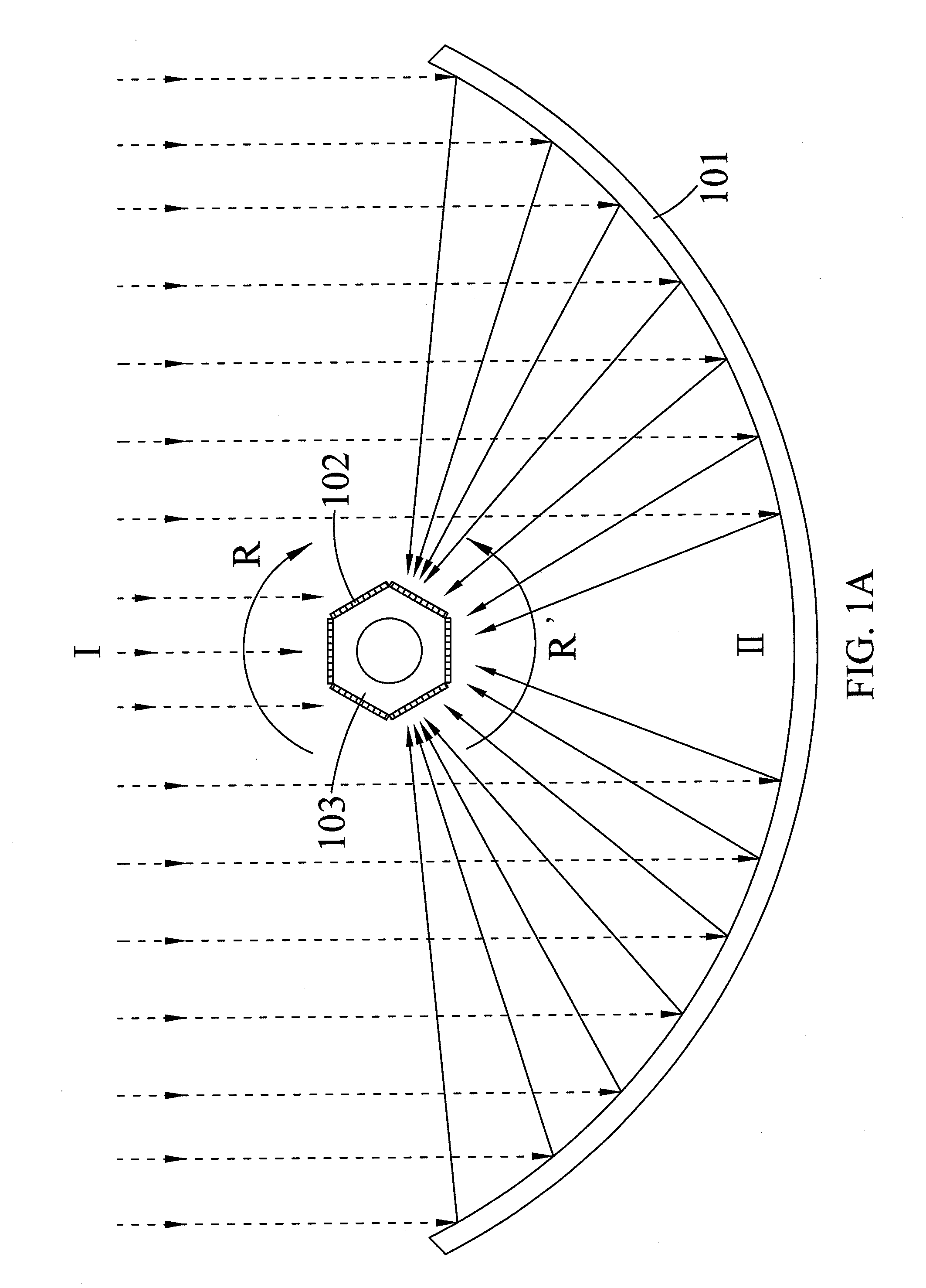
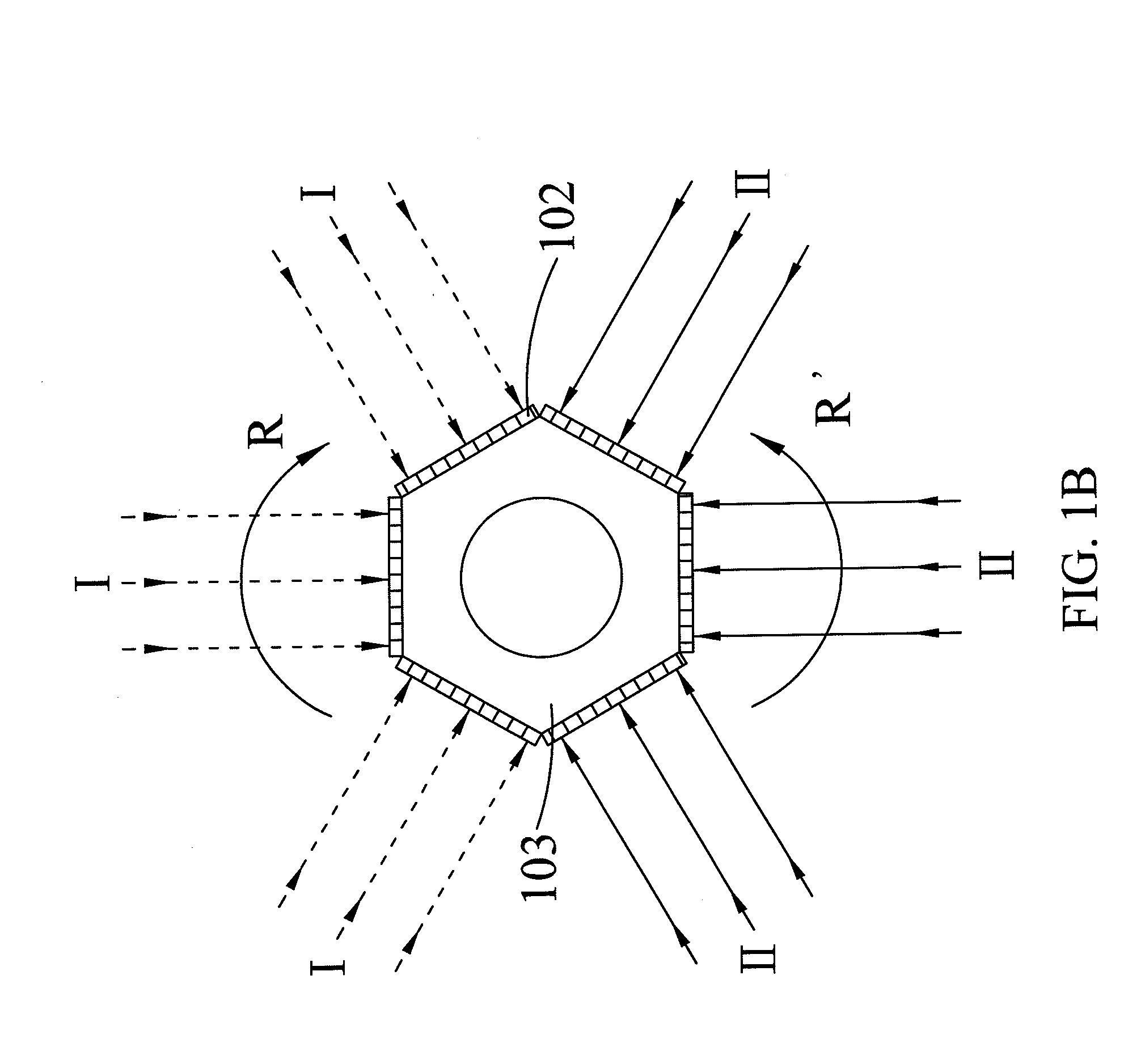
The present invention increases the power output of PV cells used with sunlight concentrating devices like parabolic reflectors. This is achieved by rotating the PV cells or cell assemblies evenly distributing concentrated sunlight radiation on the surface of the cells. This rotation also minimizes hot spots caused by the mirrors or reflectors in the concentrated system. The rotation increases convection cooling of the PV cells, leading to improved efficiency and longer cell life. By periodically rotating in and out of the focal point or focal line in the concentrated system, the PV cells cool more quickly. When PV cells are placed at different regions on the sun-facing side, they are exposed to different radiation intensities. The invention allows for increased exposure to concentrated sunlight and non-concentrated sunlight, resulting in increased overall electrical energy produced from a given installation size.

Problems solved by technology

Depending on the concentration ratios, the captured solar energy can cause excessive heating of PV cells or cell assemblies, resulting in reduced solar energy conversion efficiency by the PV cells or cell assemblies and shortened operation life of PV cells or cell assemblies.
However, although concentration of sunlight increases the output of PV cells or cell assemblies, it also heats up the PV cells or cell assemblies and affects their performance if the heat retained by the PV cells or cell assemblies cannot be dissipated efficiently.
Moreover, the life of conventional PV cells or cell assemblies is drastically shortened in long-term high-temperature operation.
Moreover, in a concentrated system, hot spots or uneven exposure to the concentrated sunlight can occur due to shifting or misalignment of the PV cells or cell assemblies with respect to the focal point of the concentrating mirror or lens system.
The hot spots or uneven exposure can affect the performance and the cell life of the solar PV system.

Method used


Image

  • Use of rotating photovoltaic cells and assemblies for concentrated and non-concentrated solar systems
  • Use of rotating photovoltaic cells and assemblies for concentrated and non-concentrated solar systems
  • Use of rotating photovoltaic cells and assemblies for concentrated and non-concentrated solar systems

Examples


Embodiment Construction

[0068]Advantages and features of the present invention and methods of accomplishing the same may be understood more readily by reference to the following detailed description of exemplary embodiments and the accompanying drawings. The present invention may, however, be embodied in many different forms and should not be construed as being limited to the embodiments set forth herein. Rather, these embodiments are provided so that this disclosure will be thorough and complete and will fully convey the concept of the invention to those skilled in the art, and the present invention will only be defined by the appended claims.

[0069]In the drawings, sizes and relative sizes of layers and regions may be exaggerated for clarity.

[0070]Embodiments of the invention are described herein with reference to cross-section illustrations that are schematic illustrations of idealized embodiments of the invention. As such, variations from the shapes of the illustrations as a result, for example, of manu...


PUM


Abstract

A concentrated and non-concentrated solar photovoltaic (PV) system with rotating PV cells or cell assemblies is provided to enhance cooling, receive both concentrated and non-concentrated sunlight, avoid hot spots and prolong PV cell operation life. The solar PV system comprises: one or more reflectors having a sun-facing side and a non-sun-facing side; and one or more rotating members with attaching PV cells or cell assemblies disposed at the sun-facing side of the reflector, herein the rotating members are able to rotate. The one or more rotating members with PV cells or cell assemblies are placed at predetermined positions at the sun-facing side of the reflector, and, during operation, the PV cells or cell assemblies has at least one light illuminated surface which is able to receive reflected light from different positions of the reflector, the direct solar radiation from the sun or the diffused solar radiation from the surroundings.

Description

CROSS-REFERENCE TO RELATED APPLICATION[0001]This application claims the benefit of US. Provisional Application No. 61 / 505,154, filed on Jul. 7, 2011, in the US. Patent and Trademark Office the disclosure of which is incorporated herein by reference.BACKGROUND OF THE INVENTION[0002]1. Field of the Invention[0003]The present invention generally relates to a solar PV system with photovoltaic (PV) cells, in particular to a solar PV system that simultaneously collects concentrated and non-concentrated sunlight with one or more rotating PV cells or cell assemblies. The PV cells or cell assemblies may form a part of a combined solar PV and solar thermal energy system.[0004]2. Description of the Related Art[0005]Solar technology deals with the use of solar energy for a multitude of practical applications. PV cells or cell assemblies convert solar energy directly into electrical energy using the Photovoltaic effect which is well known in the art.[0006]Typical solar PV cells or cell assemblie...

Claims


Application Information

Patent Timeline
IPC IPC(8): H01L31/052H01L31/058
CPCY02E10/52H01L31/0547H01L31/0521
Inventor HOLMES, JOHN W.CHENG, CHIA-CHIN
Owner HOLMES JOHN W
Why Eureka
Try Eureka