Camera flash module

a technology of flash module and camera, which is applied in the direction of lighting device details, lighting and heating apparatus, instruments, etc., can solve the problems of inability to optimize the photograph area of the camera, the light emitted in a circular shape may be difficult to be controlled, and the light efficiency may decreas

Inactive Publication Date: 2013-01-03
SAMSUNG ELECTRONICS CO LTD
View PDF12 Cites 17 Cited by
  • Summary
  • Abstract
  • Description
  • Claims
  • Application Information

AI Technical Summary

Benefits of technology

[0019]An aspect of the present invention provides a camera flash module that may adjust a direction of a light to match an angle of view of a camera.

Problems solved by technology

When a Fresnel lens that minimizes a size of a lens is used, a light emitted from a light emitting device may be difficult to be controlled and thus, a light efficiency may decrease.
Also, when a lens is provided in a circular shape, a light passing through the lens is emitted in a circular shape and thus, the light emitted in a circular shape may not be optimized for the photograph area of the camera which is provided in a quadrangular shape.
Accordingly, a light loss may significantly occur.
Accordingly, many lights are out of the photograph area of the camera and thus, a light efficiency may be low.
Also, little light is illuminated to a corner of the camera and thus, a brightness uniformity may decrease and a quality of an image may decrease.
Even though the circular side total reflection unit may be readily manufactured, a performance may be deteriorated since a size of a screen of a camera has a width to height ratio of 4:3, which is the characteristic of cameras.
However, a distance between a light emitting device and the lens is significantly greater than the integrated type and thus, energy loss may occur.
Also, a degree of distortion in a tilt and an optical axis between the light emitting device and the window lens is high and thus, an assembly error rate may increase.
However, the integrated flash lens has a drawback in its manufacturing process.
However, a camera flash module? lens is made from silicon that is robust against heat and has a low strength and thus, assembly of the light emitting device and the lens may be difficult and maintaining of the distance between the light emitting device and the lens to be constant may also be difficult.

Method used


Image

  • Camera flash module
  • Camera flash module
  • Camera flash module

Examples


Embodiment Construction

[0040]Reference will now be made in detail to embodiments of the present invention, examples of which are illustrated in the accompanying drawings, wherein like reference numerals refer to the like elements throughout. Embodiments are described below to explain the present invention by referring to the figures.

[0041]Throughout the specifications, when it is described that each of a layer, a side, a chip, and the like is formed “on” or “under” a layer, a side, a chip, and the like, the term “on” may include “directly on” and “indirectly on,” and the term “under” may include “directly under” and “indirectly under.” A standard for “on” or “under” of each element may be determined based on a corresponding drawing.

[0042]A size of each element in drawings may be exaggerated for ease of descriptions, and does not indicate a real size.

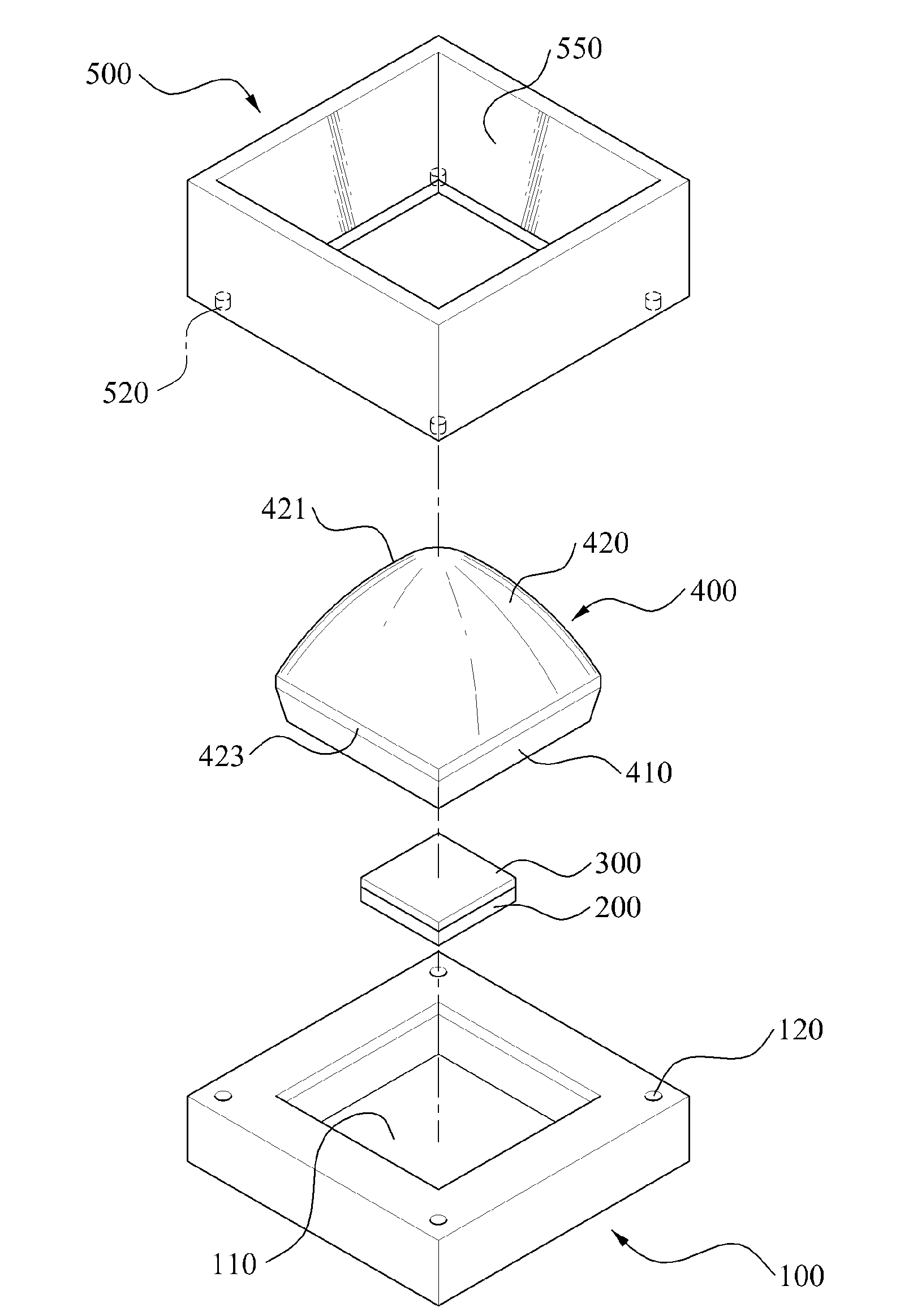
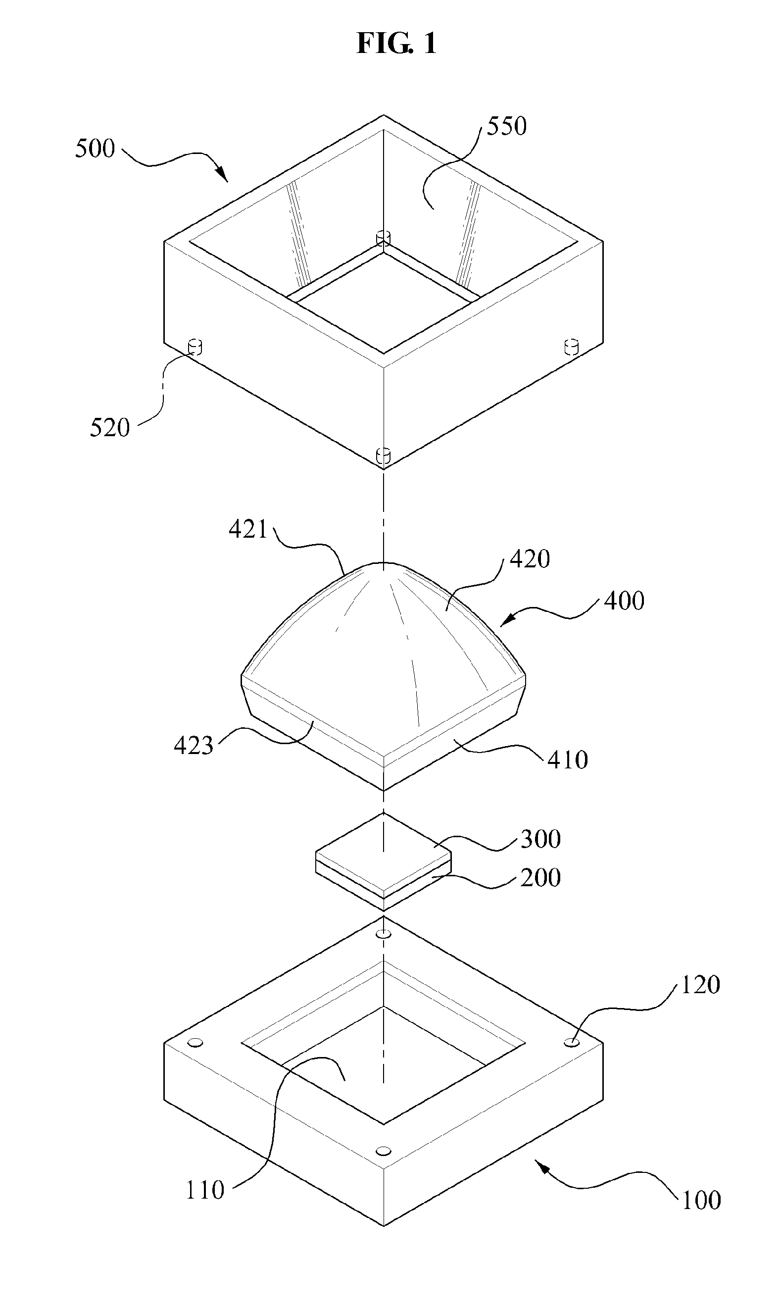
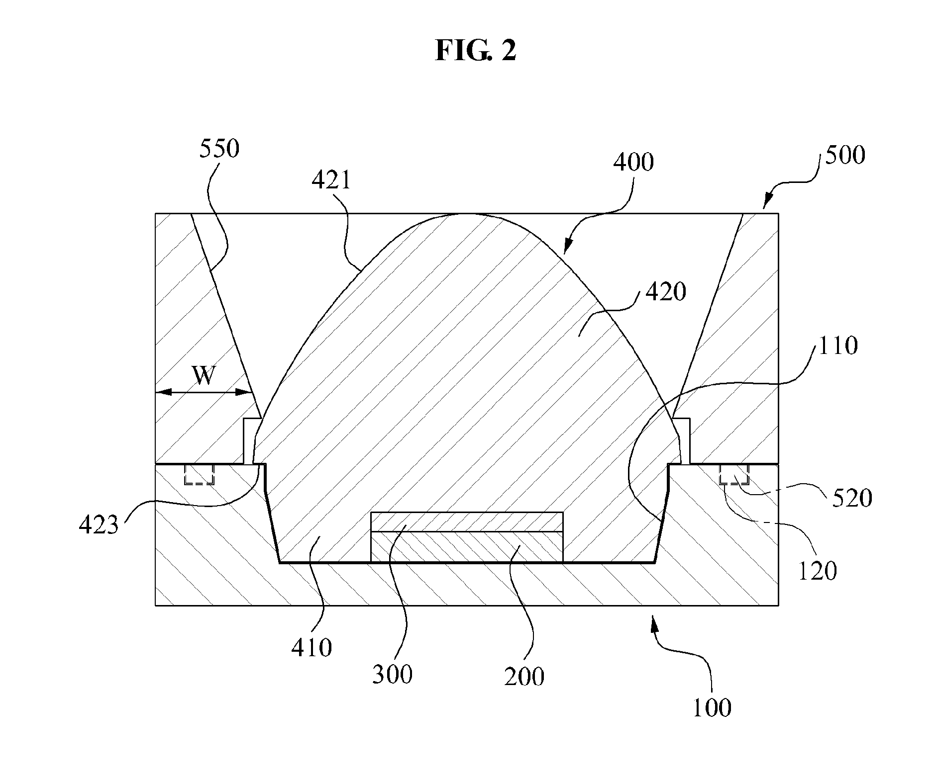
[0043]FIG. 1 illustrates a camera flash module according to an embodiment of the present invention, and FIG. 2 illustrates a cross-section of a camera flash m...


PUM


Abstract

A camera flash module is provided. The camera flash module may include a lens having a single refractive surface and a reflector that adjusts a direction of a light emitted from the lens. Accordingly, maintaining of a distance between a light emitting device and the lens may not be needed and thus, the camera flash module may be readily manufactured and a productivity may be improved. An error rate caused by distortion in a tilt and an optical axis between the light emitting device and the lens may be reduced. The reflector may adjust a direction of a light emitted from the lens and thus, an emission pattern requested by a camera may be satisfied, and a velocity of light may be improved. The reflector may surround the lens and thus, may prevent the lens from being detached from a light emitting device package body when an external impact occurs.

Description

CROSS-REFERENCE TO RELATED APPLICATION[0001]This application claims the benefit of Korean Patent Application No. 10-2011-0065442, filed on July. 1, 2011, in the Korean Intellectual Property Office, the disclosure of which is incorporated herein by reference.BACKGROUND[0002]1. Field of the Invention[0003]The present invention relates to a camera flash module, and more particularly, to a camera flash module that may adjust a direction of a light so as to match an angle of view of a camera.[0004]2. Description of the Related Art[0005]As digital cameras have been popular, various mobile communication terminals containing a built-in small-digital camera have been manufactured and provided in the market.[0006]Digital cameras, built-in cameras of mobile terminals, and the like may contain a flash that provides an amount of light required for photographing images at night. A camera flash module is contained in most mobile communication terminals that are currently produced, so that users ma...

Claims


Application Information

Patent Timeline
Patent Type & Authority Applications(United States)
IPC IPC(8): F21V13/04
CPCG03B15/05G03B2215/0582G03B2215/0592G03B15/03H04N23/00
Inventor YOU, JAE SUNG
Owner SAMSUNG ELECTRONICS CO LTD
Why Eureka
Try Eureka