
Devices and processes for data input

a data input and touch-sensitive technology, applied in the direction of electric digital data processing, instruments, computing, etc., can solve the problems of touch-sensitive location of interest, user may lose the position of touch-sensitive location, touch-sensitive location of interest, etc., to achieve the effect of reducing the likelihood of simultaneous conta

Inactive Publication Date: 2013-01-03
TEN ONE DESIGN
View PDF6 Cites 28 Cited by
  • Summary
  • Abstract
  • Description
  • Claims
  • Application Information

AI Technical Summary

Benefits of technology

This patent is about a new invention that provides a way to input data on touch-sensitive devices. The invention allows for precise and accurate input by using a physical button that the user can touch or touch with another touch. This eliminates the risk of accidentally touching multiple locations at once and activating unintended functions. The invention is easy to use and works across a range of devices. The contact with the button is the only way to determine the position of the user's touch, so the invention is also more precise. Overall, the invention enables effective and precise data input on touch-sensitive devices.

Problems solved by technology

As a result, the user may lose the position of the touch-sensitive location, or may not recognize the feeling provided when the location is pushed.
Additionally, a touch-sensitive location of interest that does not exhibit tactile feeling may be difficult to locate when a user is concentrating on another portion of the screen, for example, the content of a game instead of the controls for the game.
A further drawback of such technology insofar as there are multiple touch locations is that more than one of those locations may be touched or otherwise contacted simultaneously during operation of the device, resulting in activation of an unwanted function (“multiple simultaneous touches”).
This is inconvenient and slows operation of the device, but is not practically speaking avoidable if a user's execution of discrete touches or contacts at desired different locations is to be achieved.
However, the foregoing technology is disadvantageously limited.
While some embodiments mentioned in the 403 Publication comprise a button actuator structure having an airgap between an actuation area and a touch-screen's touch-sensitive location, with the result that a substantial force must be applied to the actuator area to cause contact with the touch-sensitive location, there is no assurance that this will be accompanied by a “feel” which indicates to the user that contact is effected.
Moreover, a fixed structure is effectively anchored at one site, and cannot be moved to any other location on the surface, during “real time” operation of the data processing device.
And, in any event, a fixed structure cannot be operated by a user for the purpose of data input to indicate direction or magnitude of motion of an object or avatar, such as while playing a game.
This also tends to interfere with their configuration in such manner as to facilitate the desired discrete access, and concomitant ready initiation of intended functions with precision.
First, since the joystick actuator is arranged such that the portion directly beneath the pivot point is occupied by an attachment portion, this configuration does not allow for input to be generated, or buttons to be actuated, in or from the center position of the joystick.
Second, such a configuration could only be operative with discrete input regions, and not input regions simulating joysticks.
Third, since the joystick relies on attachment portions that actuate fixed position button attachments, the disclosed configuration cannot indicate the magnitude of motion of an object or avatar, such as while playing a game.
But, it is explained that even if “a simple decal is provided over the touch pad to indicate the location of dedicated touch controls”, the user must still examine the interface surface during use to identify the location, which slows productivity.
It is further noted that advanced touch sensing devices do not provide an indication of when there has been a successful touch input.
Although both of the 403 and 090 Publications purport to disclose improved technologies whereby a mechanical or other element is operated by a user to exert force upon a touch-sensitive location of a touch pad, touch screen or other interface, both of them fall short.
This has drawbacks from the standpoint of incapacity to provide a lack of “feel” to the user concerning whether contact has resulted in data input.In U.S. Pat. No. 7,391,410 (the “410 patent”) there is disclosed a movement input device comprising a touchscreen contact part which protrudes from the bottom side of a unit for fastening the movement input device to a portable electronic device that includes a touchscreen.
Nevertheless, there is an absence of teaching as to a data entry element which is movable over the face of the touch screen in other than angular fashion.
The input tool is said to be for enabling directional input, but has an intricate construction and (from all that appears) a limited range of motion.
Additionally, the input tool may disrupt clear views of the detection unit surface thereunder.
Furthermore, this input device does not appear to return automatically to a center position of the interface region's range of motion.
However, for reasons explained already in connection with the 090 Publication, the reported development falls short inasmuch as there is no provision for “real time” movement of the switch from one location to another on the touchscreen.

Method used


Image

  • Devices and processes for data input
  • Devices and processes for data input
  • Devices and processes for data input

Examples


Embodiment Construction

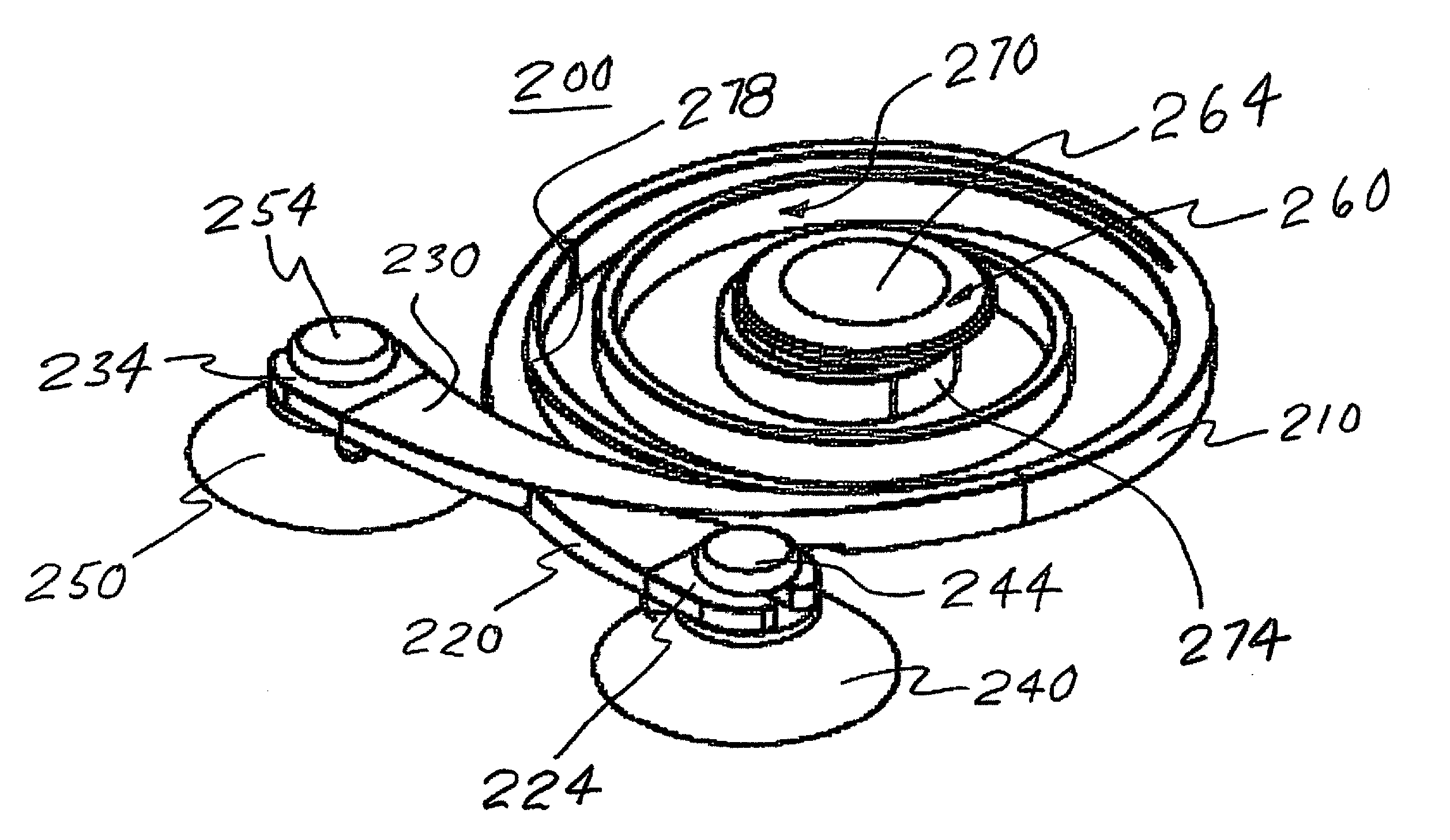
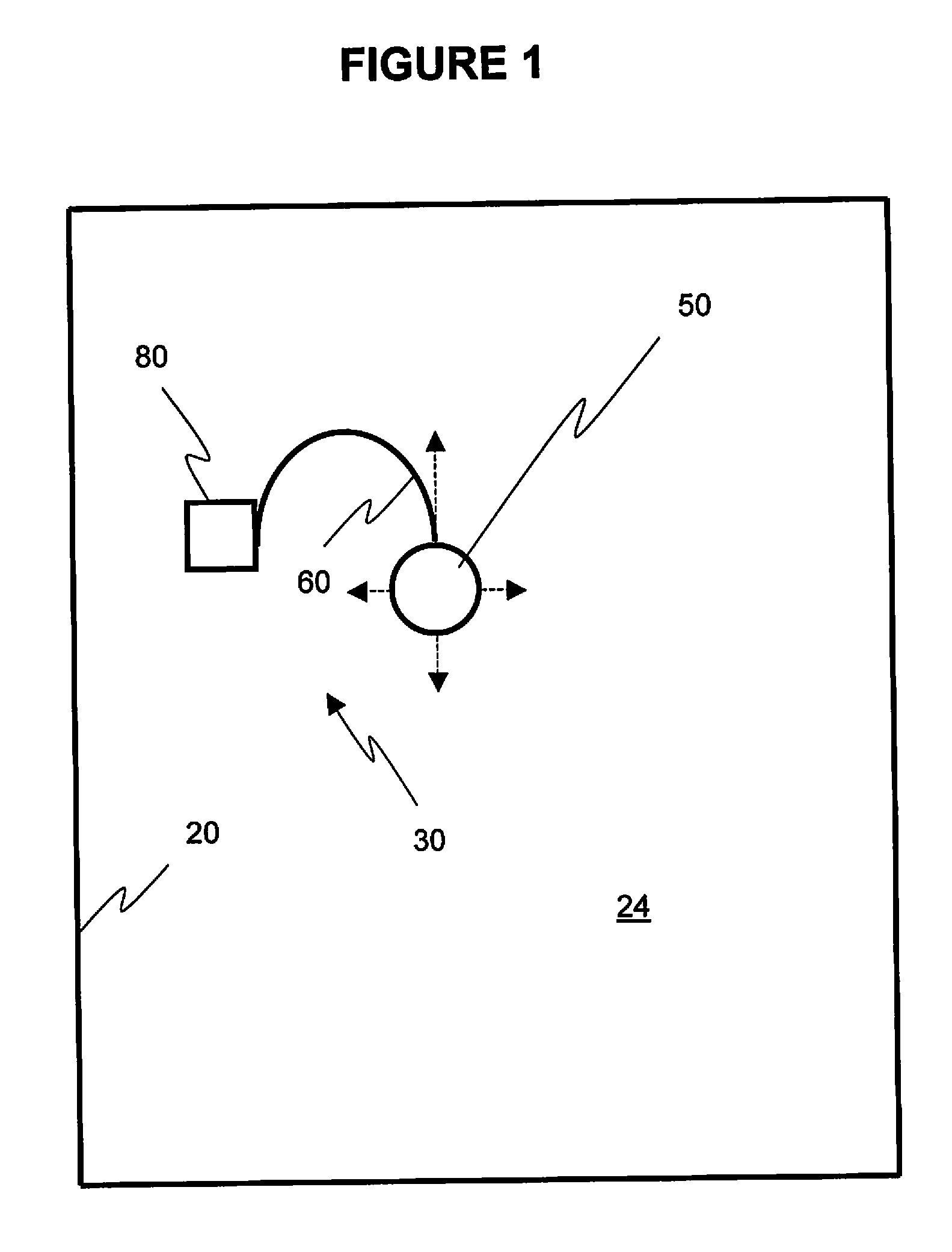
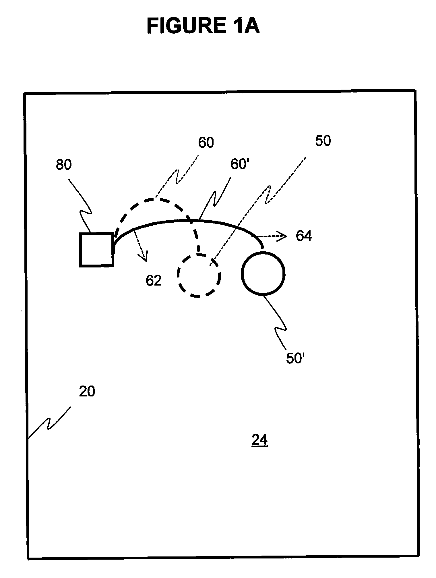
[0038]A central feature of the invention is the incorporation of a movable button which when force is applied thereto comes into electrical contact with a touch-sensitive location on an electrically sensitive user interface surface. The advantageous mounting structure for the button—a member, especially a segmented arm—affords the desired range of motion. Effecting contact via a button provides the necessary user feedback concerning achievement of such contact. Moreover, in this manner, the button can readily be translated across the surface in “real time” during use. This means that not only is the button accurately positionable over a single touch-sensitive location, it further can be positioned over each of a plurality of them in sequence, one at a time, without unintended touching of another location on the surface.

[0039]The invention is useful with the general category of data processing devices comprising an electrically sensitive user interface surface, for instance, a touchs...


PUM


Abstract

Devices are disclosed for inputting data to a touch sensitive user interface, which devices comprise a base operative to affix to the user interface, a button having an outer touch surface and an inner surface operative to engage the user interface to convey a data input signal thereto in response to presence of a user's finger at the outer touch surface of the button, and an arm connecting the button to the base; processes for data input are also disclosed.

Description

PRIORITY INFORMATION[0001]The priority of U.S. Provisional Application No. 61 / 429,247, filed Jan. 3, 2011, is claimed, the subject matter of such provisional application being incorporated herein by reference.FIELD OF THE INVENTION[0002]The present invention concerns the input of data to a touch-sensitive user interface, such as the touch screen for a computer, mobile telephone, or hand-held data processing device.BACKGROUND OF THE INVENTION[0003]Portable electronic devices typically comprise a touchpad or touch screen display, or other interface system capable of detecting the location of contact with the interface. Touching or otherwise contacting the touchpad, touch screen or other interface at a particular location causes the electronic device to perform a particular function. The touch pad, touch screen or other interface of such a device typically has one or more touch-sensitive locations.[0004]However, it can be a shortcoming of the touch-sensitive location that it does not e...

Claims


Application Information

Patent Timeline
IPC IPC(8): G06F3/041
CPCG06F3/03547G06F3/0338
Inventor SKINNER, PETER JAMES
Owner TEN ONE DESIGN
Learn More