
Horizontal stabilizer trim actuator failure detection system and method using position sensors

Active Publication Date: 2013-01-03
PARKER HANNIFIN CORP
View PDF17 Cites 29 Cited by
  • Summary
  • Abstract
  • Description
  • Claims
  • Application Information

AI Technical Summary

Benefits of technology

The technology described in this patent simplifies the design and reduces the weight, size, and cost of detecting failures in mechanical systems. It also makes it easier for ground crews to reset the systems. In some applications, the technology takes advantage of unidirectional loads.

Problems solved by technology

Failures of the primary load path such as caused by the shearing off of the connecting trunnion segment or by the loss of nut ball members from the ball nut assembly can result in the complete loss of control of the horizontal stabilizer.

Method used


Image

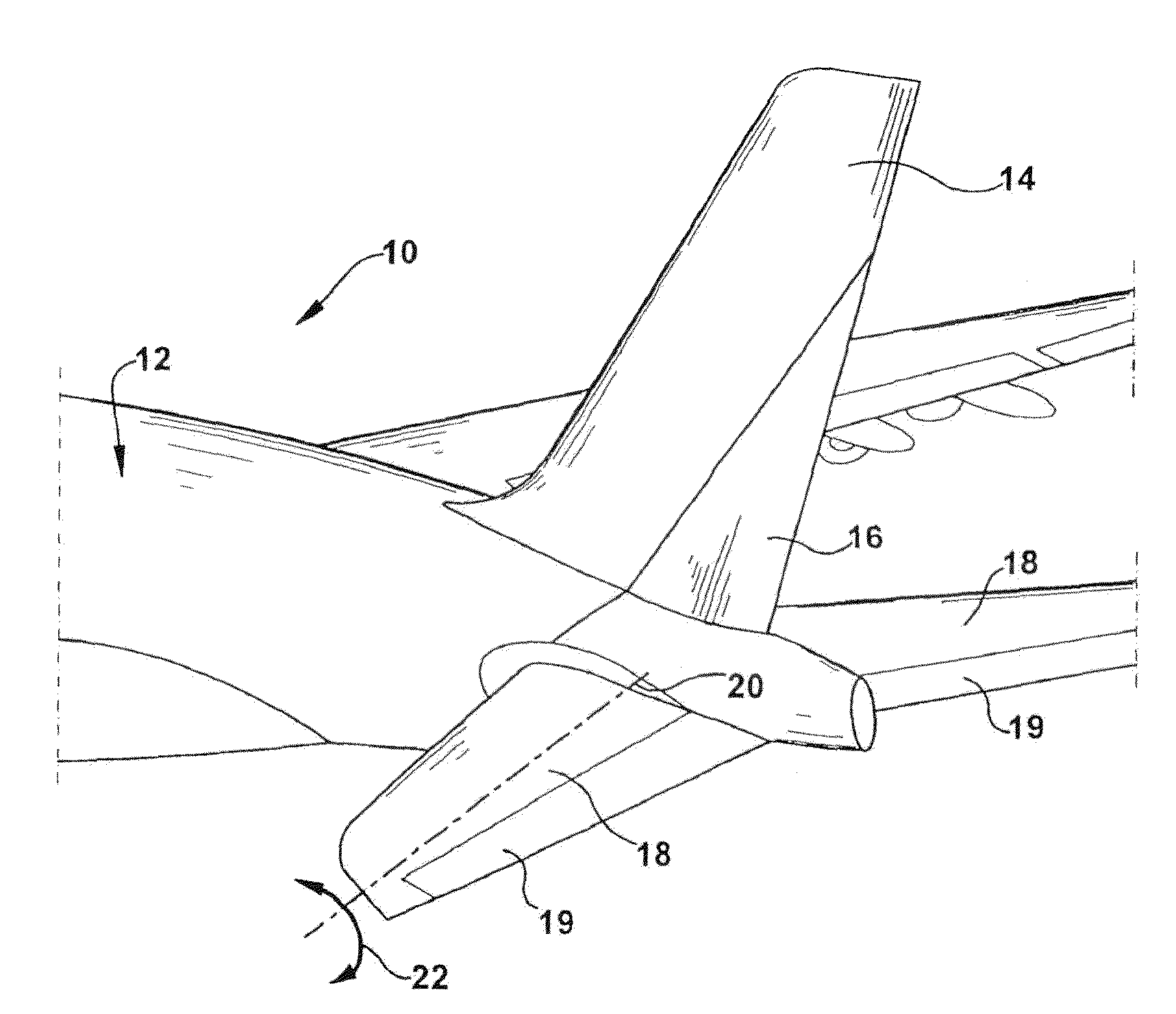
  • Horizontal stabilizer trim actuator failure detection system and method using position sensors
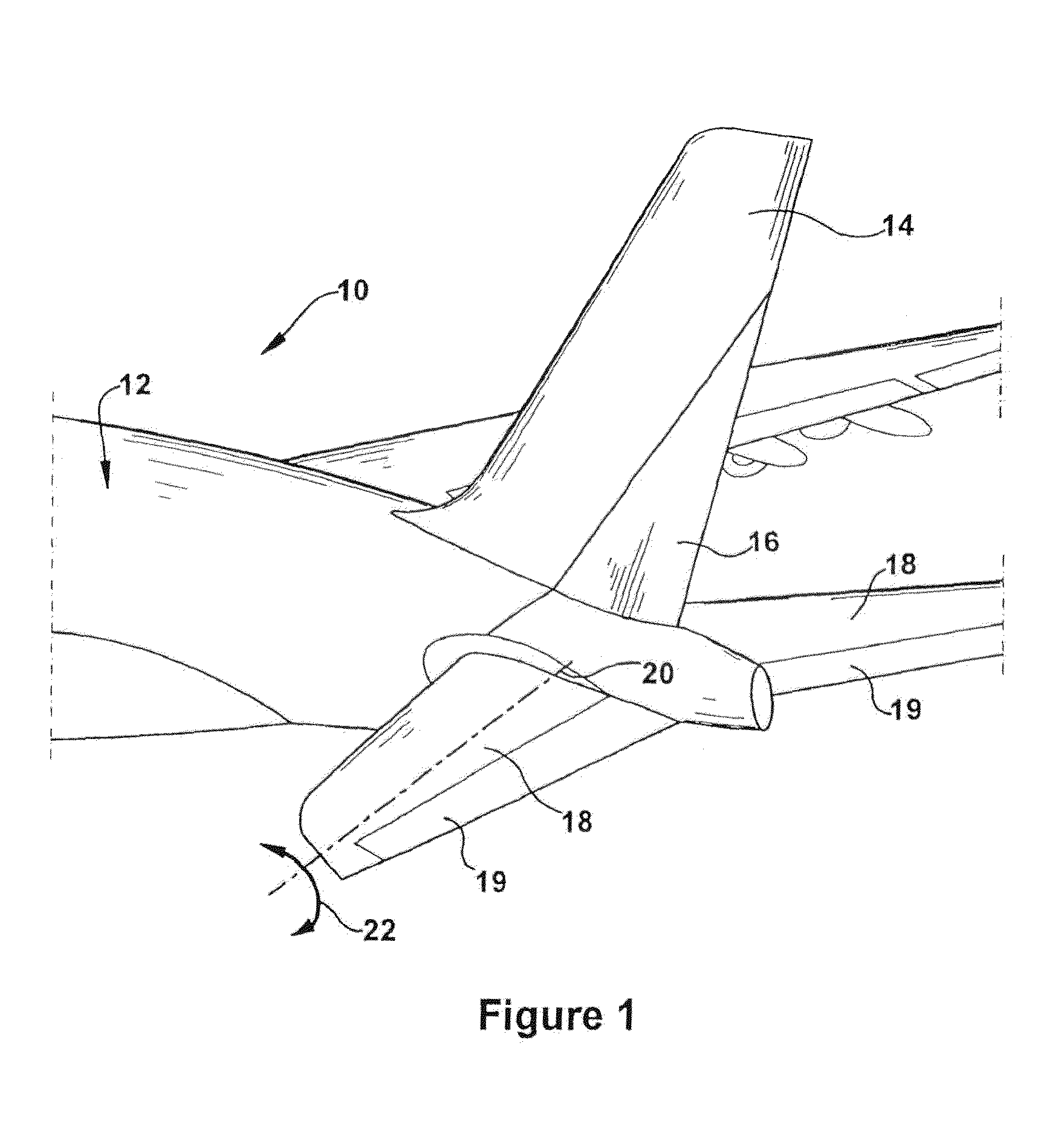
  • Horizontal stabilizer trim actuator failure detection system and method using position sensors
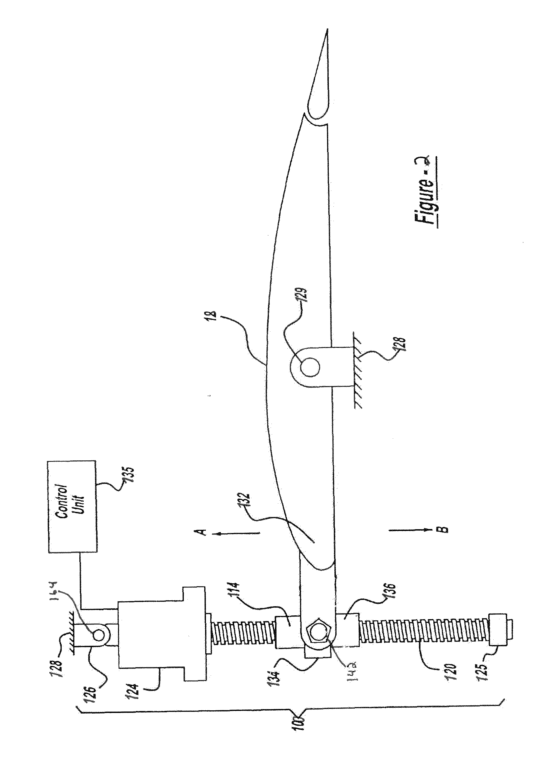
  • Horizontal stabilizer trim actuator failure detection system and method using position sensors

Examples


Embodiment Construction

[0041]The sensors described herein can be continuous (as may be required by certification authorities) and can convey signals to the pilot and / or a flight log indicating the detection (or non-detection) of drive-path failure. They may be any appropriate sensor such as an electrical switch, a mechanical position sensor (such as a linear variable differential transducer), Hall-effect sensor, linear encoder, or the like, or even a combination thereof. For the sake of brevity, one particular embodiment is described herein, so the sensors will be referred to, herein, as linear variable differential transducers (LVDT). However, it will be understood that any appropriate sensor could be used, instead.

[0042]The motion provider for the actuator described herein need not be an electric motor and / or the assembly 40 need not include rotational members such as the ballscrew and the ball nut. The motion provider could instead comprise hydraulic and / or pneumatic cylinders, or any other device whic...


PUM


Abstract

An actuator assembly having a primary load path for tightly coupling an actuated surface to a reference structure and a secondary load path having a backlash portion for coupling the actuated surface to the reference structure with backlash, wherein the secondary load path is unloaded during an operative state of the primary load path and loaded during a failure state of the primary load path. The actuator assembly includes at least one sensor configured to sense the failure state of the primary load path when a relative displacement between a portion of the primary load path and a portion of the secondary load path exceeds a predetermined value or is within a predetermined range of values.

Description

RELATED APPLICATIONS[0001]This application claims the benefit of U.S. Provisional Application No. 61 / 503,288 filed Jun. 30, 2011, which is hereby incorporated herein by reference.FIELD OF INVENTION[0002]The present invention relates generally to determining mechanical failures in actuators having a primary and a secondary load path, and more particularly to detecting failures in the primary load path of actuators for aircraft stabilizers.BACKGROUND[0003]Modern aircraft have horizontal stabilizers located at the tail section of the fuselage or the rudder section that are pivotally supported relative to the airplane fuselage to “trim” the aircraft during flight by selective adjustment by the operator or pilot from an internal control unit. This involves adjusting the position of the horizontal stabilizer by a stabilizer actuator to accommodate different load distributions within the aircraft and different atmospheric conditions, i.e. wind, rain, snow, etc. In this regard the stabilize...

Claims


Application Information

Patent Timeline
IPC IPC(8): B64C13/42G05B11/32
CPCB64C13/42B64C13/28
Inventor CYROT, LUC P.
Owner PARKER HANNIFIN CORP
Learn More