
Programmable mechanism for delayed synchronous data reception

Active Publication Date: 2012-12-27
VIA TECH INC
View PDF5 Cites 6 Cited by
  • Summary
  • Abstract
  • Description
  • Claims
  • Application Information

AI Technical Summary

Benefits of technology

[0012]The present invention, among other applications, is directed to solving the above-noted problems and addresses other problems, disadvantages, and limitations of the prior art. In addition, the present invention provides a superior technique for optimizing the transmission and reception of source synchronous signals in disparate devices such as microprocessors and their support devices. In one embodiment, an apparatus is provided that compensates for misalignment on a synchronous data bus. The apparatus includes a Joint Test Action Group (JTAG) interface, a synchronous bus opt

Problems solved by technology

But data strobes and data signals are subject to error for a number of reasons.
One source of error is inaccuracies of associated clock generation circuits, typically phase locked loops, that are employed to gate the data signals onto the bus and to switch the strobes to indicate that the data is valid.
These inaccuracies may be the result of design margins, fabrication tolerances, or environmental factors.
And inaccuracies in the associated clock generation circuits may result in skewing of the data signals and / or their strobes such that reception conditions are not optimum.
Another source of error caused by distribution of a strobe signal within a receiving device.
In some devices, the additional propagation lengths that are required to route the strobe to various receivers may add delay over that of the data signals, thereby skewing the phase of the synchronous transmission.

Method used


Image

  • Programmable mechanism for delayed synchronous data reception
  • Programmable mechanism for delayed synchronous data reception
  • Programmable mechanism for delayed synchronous data reception

Examples


Embodiment Construction

[0024]The following description is presented to enable one of ordinary skill in the art to make and use the present invention as provided within the context of a particular application and its requirements. Various modifications to the preferred embodiment will, however, be apparent to one skilled in the art, and the general principles defined herein may be applied to other embodiments. Therefore, the present invention is not intended to be limited to the particular embodiments shown and described herein, but is to be accorded the widest scope consistent with the principles and novel features herein disclosed.

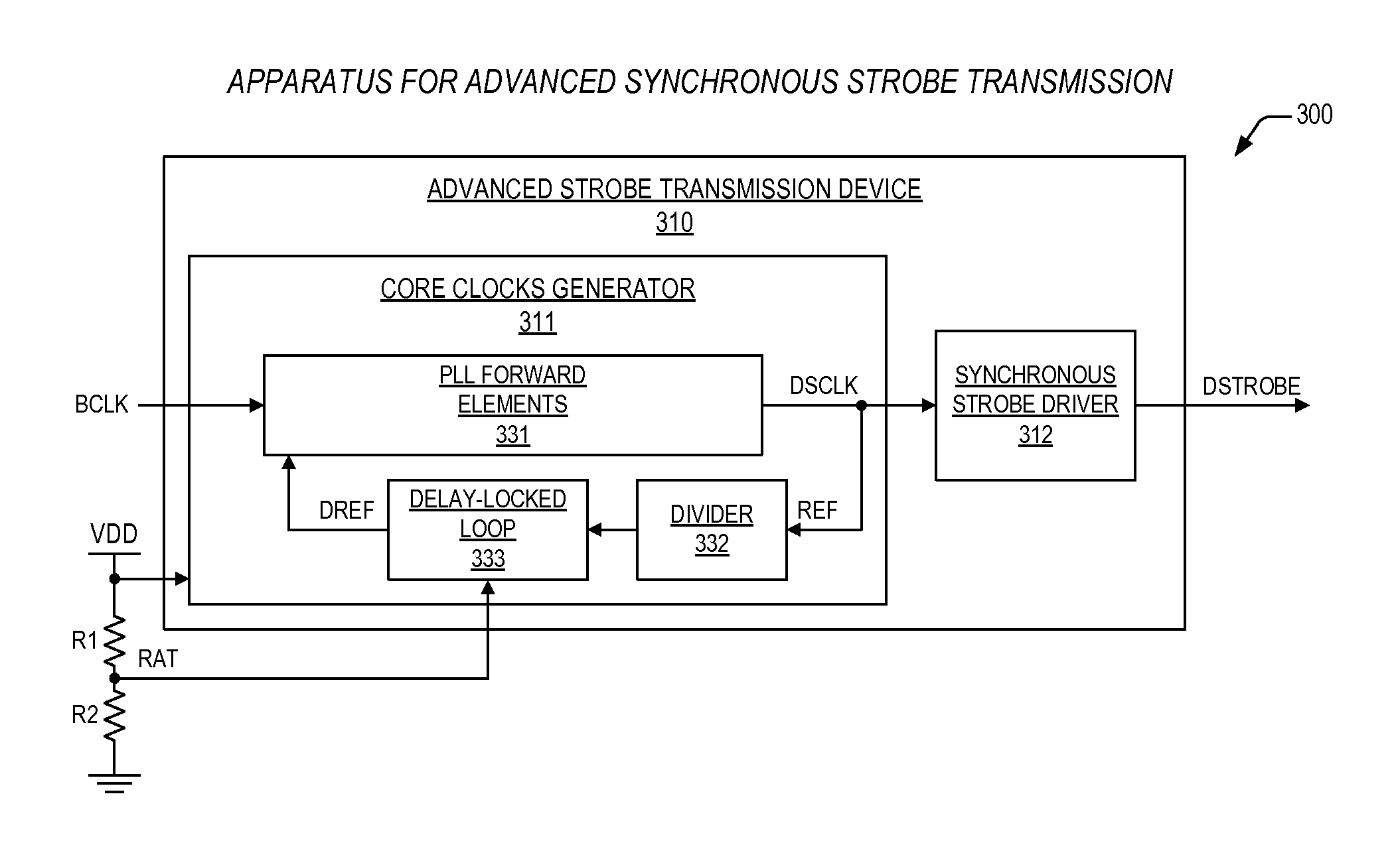
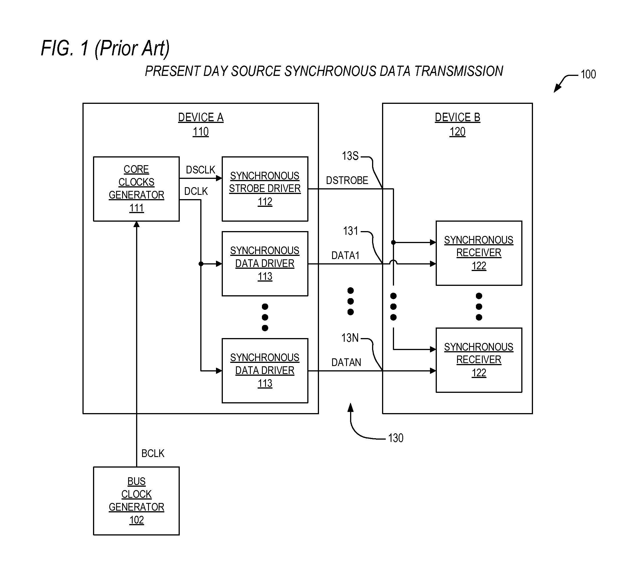
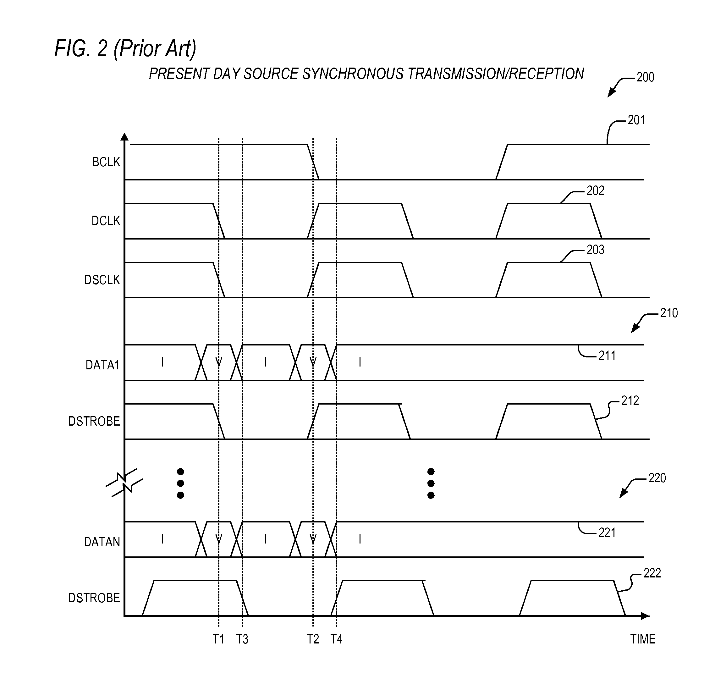
[0025]In view of the above background discussion on source synchronous signaling and associated techniques employed within present day devices for the transmission and reception of data, a discussion of the disadvantages and limitations of the present day techniques be discussed with reference to FIGS. 1-2. Following this, a discussion of the present invention will be presented...


PUM


Abstract

An apparatus is provided that compensates for misalignment on a synchronous data bus. The apparatus includes a Joint Test Action Group (JTAG) interface, a synchronous bus optimizer, and a delay-locked loop (DLL). The JTAG interface is configured to receive control information over a standard JTAG bus, where the control information indicates an amount to delay a data bit signal associated with a data group. The synchronous bus optimizer is configured to receive the control information, and is configured to develop a value on a ratio bus that indicates the amount. The DLL is coupled to the ratio bus, and is configured generate a delayed data bit signal, where the DLL adds the amount of delay to the data bit signal to generate the delayed data bit signal.

Description

CROSS-REFERENCE TO RELATED APPLICATIONS[0001]This application is related to the following co-pending U.S. patent applications, each of which has a common assignee and common inventors.SERIALFILINGNUMBERDATETITLE      Jun. 21, 2011APPARATUS AND METHOD FOR(CNTR.2321)ADVANCED SYNCHRONOUSSTROBE TRANSMISSION      Jun. 21, 2011OPTIMIZED SYNCHRONOUS(CNTR.2538)STROBE TRANSMISSIONMECHANISM      Jun. 21, 2011APPARATUS AND METHOD FOR(CNTR.2542)DELAYED SYNCHRONOUS DATARECEPTION      Jun. 21, 2011OPTIMIZED SYNCHRONOUS DATA(CNTR.2543)RECEPTION MECHANISM      Jun. 21, 2011PROGRAMMABLE MECHANISM(CNTR.2544)FOR SYNCHRONOUS STROBEADVANCE      Jun. 21, 2011PROGRAMMABLE MECHANISM(CNTR.2567)FOR OPTIMIZING ASYNCHRONOUS DATA BUSBACKGROUND OF THE INVENTION[0002]1. Field of the Invention[0003]This invention relates in general to the field of microelectronics, and more particularly to an apparatus and method for synchronizing and clocks and data related to the transmission and reception of source synchronous ...

Claims


Application Information

Patent Timeline
IPC IPC(8): G06F1/12
CPCG06F13/00G06F13/423
Inventor GASKINS, DARIUS D.LUNDBERG, JAMES R.
Owner VIA TECH INC
Learn More