
Illumination apparatus

Active Publication Date: 2012-12-27
PANASONIC CORP
View PDF4 Cites 25 Cited by
  • Summary
  • Abstract
  • Description
  • Claims
  • Application Information

AI Technical Summary

Benefits of technology

[0005]In view of the above, the present invention provides an illumination apparatus capable of suppressing power consumption while maintaining a function of detecting a presence or absence of a human.
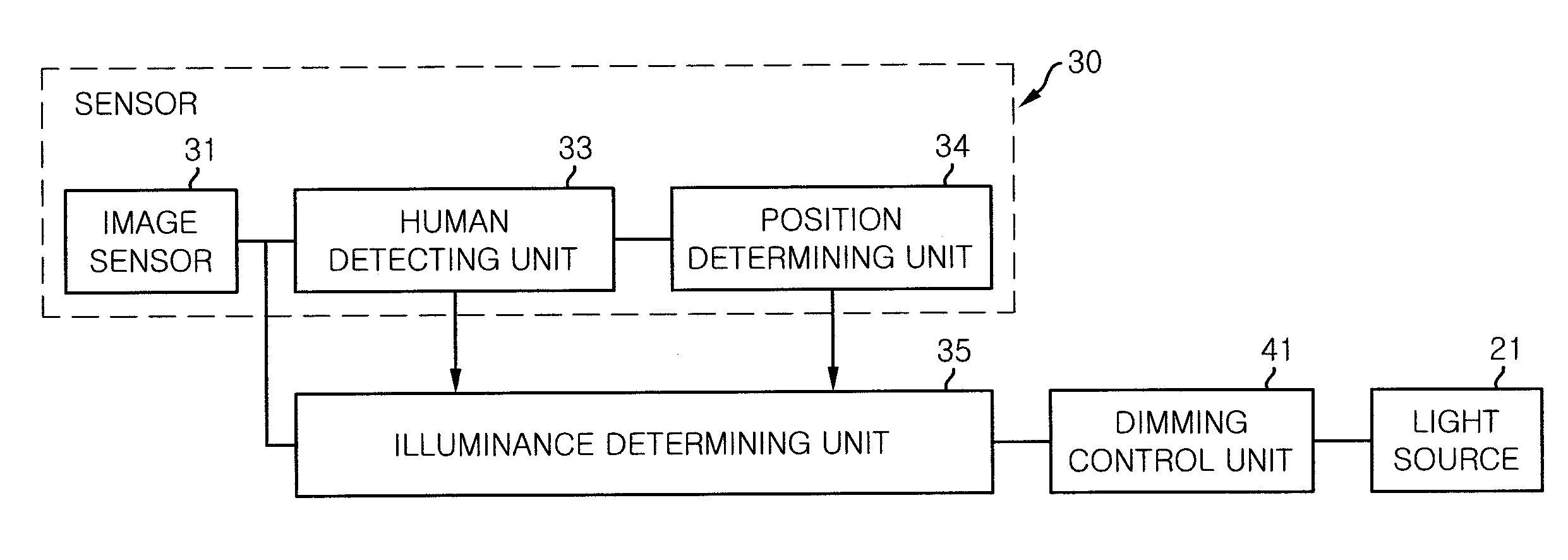
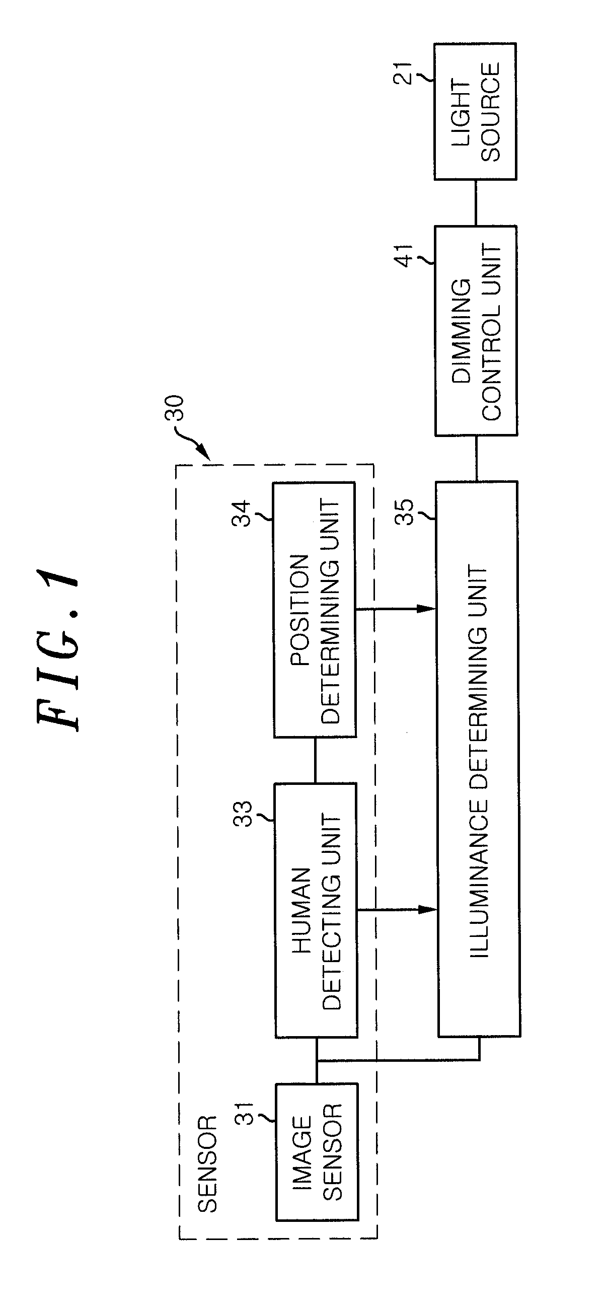
[0007]The illuminance determining unit obtains an illuminance of an illuminance maintaining area included in the visual field based on the image captured with the image sensor, and when the sensor detects that no human is present, the illuminance determining unit reduces the light output from the light source while maintaining the illuminance of the illuminance maintaining area to be equal to or greater than a threshold that is set in advance as a lower limit illuminance which makes it feasible for the image sensor to capture an image.
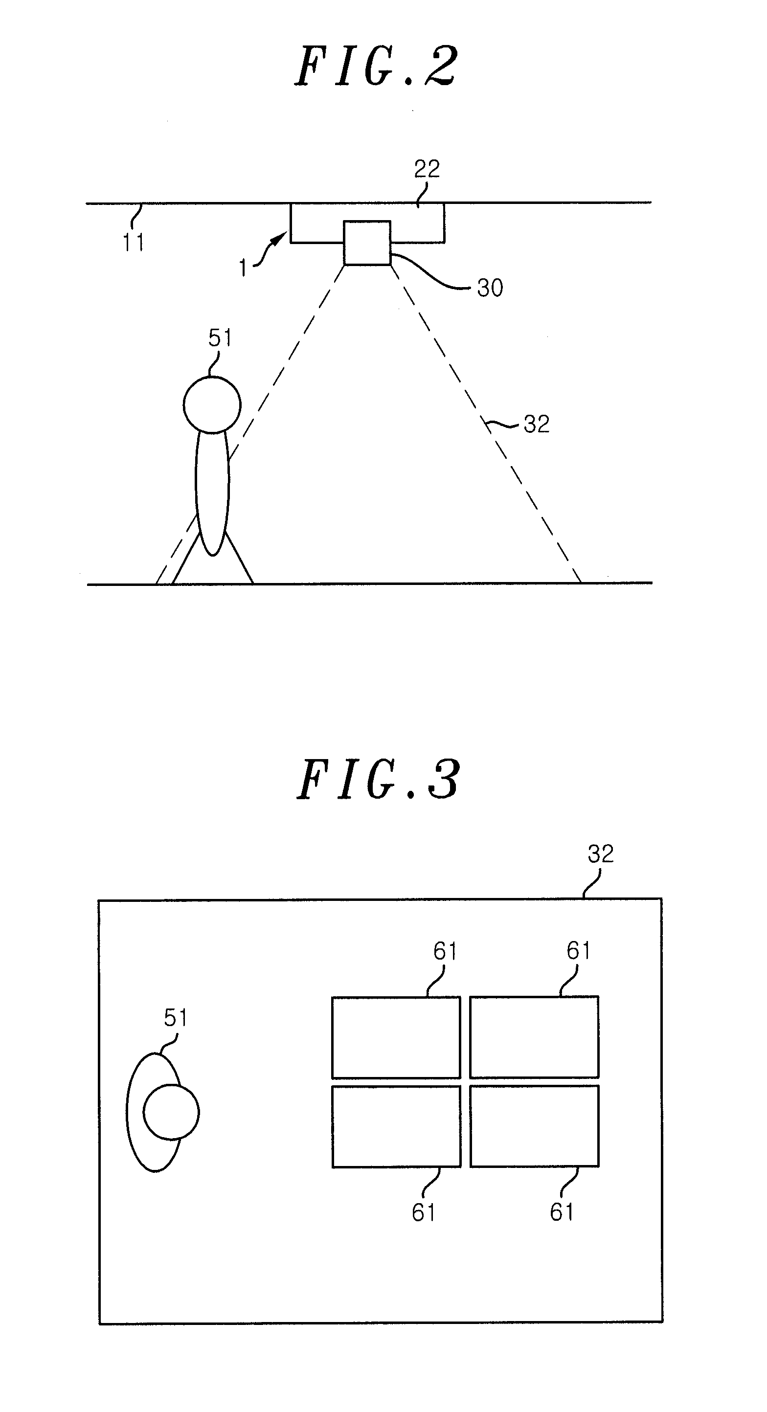
[0010]Further, the visual field may include two or more illuminance maintaining areas, and when the sensor detects that no human is present, the illuminance determining unit may obtain a prediction illuminance of each of the illuminance maintaining areas in case of reducing the light output from the light source by a predetermined value set in advance. If the prediction illuminances for all the illuminance maintaining areas are equal to or greater than the threshold, the illuminance determining unit may reduce the light output from the light source by the predetermined value.
[0011]In accordance with the present invention, there is an effect of suppressing power consumption while maintaining a function of detecting the presence or absence of a human

Problems solved by technology

However, if the light source is turned off, e.g., at night time at which a light (e.g., external light) other than a light from the light source is not incident, it becomes difficult to ensure the illuminance required for the image sensor to capture an image.
In this way, when the image sensor cannot capture an image, the detection of the presence or absence of a human by using the image cannot be accomplished.

Method used


Image

  • Illumination apparatus
  • Illumination apparatus
  • Illumination apparatus

Examples


Embodiment Construction

[0022]Hereinafter, a lighting fixture 1 including a fixture body 22 formed integrally with a sensor 30 as shown in FIG. 2 will be described as an example of an illumination apparatus. The lighting fixture 1 of the present embodiment is installed on a ceiling 11 of a room such as an office. All or a part of the room is set as an illumination range, and a presence or absence of a human and the illuminance in the illumination range are detected with the sensor 30.

[0023]If the sensor 30 determines that no human is present, the lighting fixture 1 reduces a light output from a light source 21 on the basis of the detected illuminance while maintaining the sensor 30's function of detecting the presence or absence of a human. Accordingly, the lighting fixture 1 can achieve an energy saving by suppressing the unnecessary power consumption.

[0024]As shown in FIG. 1, the sensor 30 includes an image sensor 31 having an area type image sensor such as a CCD or a CMOS image sensor and an image-captu...


PUM


Abstract

An illumination apparatus includes a light source; a sensor which has an image sensor and detects an illuminance and a presence of a human based on a captured image while setting a range overlapping a range illuminated by the light source as a visual field; an illuminance determining unit for varying a light output from the light source based on the illuminance and the presence of a human; and a dimming control unit. The illuminance determining unit obtains an illuminance of an illuminance maintaining area included in the visual field based on the captured image, and when the sensor detects no human, the illuminance determining unit reduces the light output while maintaining the illuminance of the illuminance maintaining area to be equal to or greater than a threshold that is set in advance as a lower limit illuminance, which makes it feasible for the image sensor to capture an image.

Description

FIELD OF THE INVENTION[0001]The present invention relates to an illumination apparatus which detects an illuminance and a presence or absence of a human by using an image sensor, and controls a light output from a light source based on the detection results.BACKGROUND OF THE INVENTION[0002]Conventionally, there has been provided an illumination apparatus which detects an illuminance and a presence or absence of a human by using an image sensor, and controls a light output from a light source based on the detection results (see, e.g., Japanese Patent Application Publication No. 2002-289377).[0003]The illumination apparatus described in Japanese Patent Application Publication No. 2002-289377 includes a TV camera (image sensor) using a charge coupled device (CCD), a complementary metal oxide semiconductor (CMOS) or the like, and detects the illuminance and the presence or absence of a human on the basis of an image captured by the image sensor. This illumination apparatus controls the ...

Claims


Application Information

Patent Timeline
IPC IPC(8): H05B37/02
CPCY02B20/44H05B37/0227H05B47/125Y02B20/40
Inventor NANAHARA, ATUOMATSUDA, SHINJI
Owner PANASONIC CORP
Learn More