
Conveying apparatus

a technology of conveying apparatus and auxiliary components, which is applied in the direction of vehicle maintenance, electric propulsion mounting, transportation and packaging, etc., can solve the problems of deformation of the battery unit and the vehicle body, heavy weight of the battery unit of the electrical vehicle or the like,

Inactive Publication Date: 2012-12-27
TOYOTA IND CORP
View PDF3 Cites 22 Cited by
  • Summary
  • Abstract
  • Description
  • Claims
  • Application Information

AI Technical Summary

Benefits of technology

The present invention provides a conveying apparatus for attaching a battery unit to a vehicle body that ensures attachment without enlarging the conveying apparatus. The apparatus includes mounts on the vehicle body and individual lifting mechanisms that individually lift the mounts to position the battery unit. The individual control unit controls the lifting mechanisms to ensure the battery unit is positioned correctly. The apparatus allows for stable attachment of the battery unit to the vehicle body without compromising the position of the battery unit. The apparatus can be used with different types of battery units and vehicles.

Problems solved by technology

In particular, the battery unit of an electrical vehicle or the like is heavy.
However, the heavy battery unit causes deformations in the battery unit and the vehicle body.

Method used


Image

  • Conveying apparatus
  • Conveying apparatus
  • Conveying apparatus

Examples


Embodiment Construction

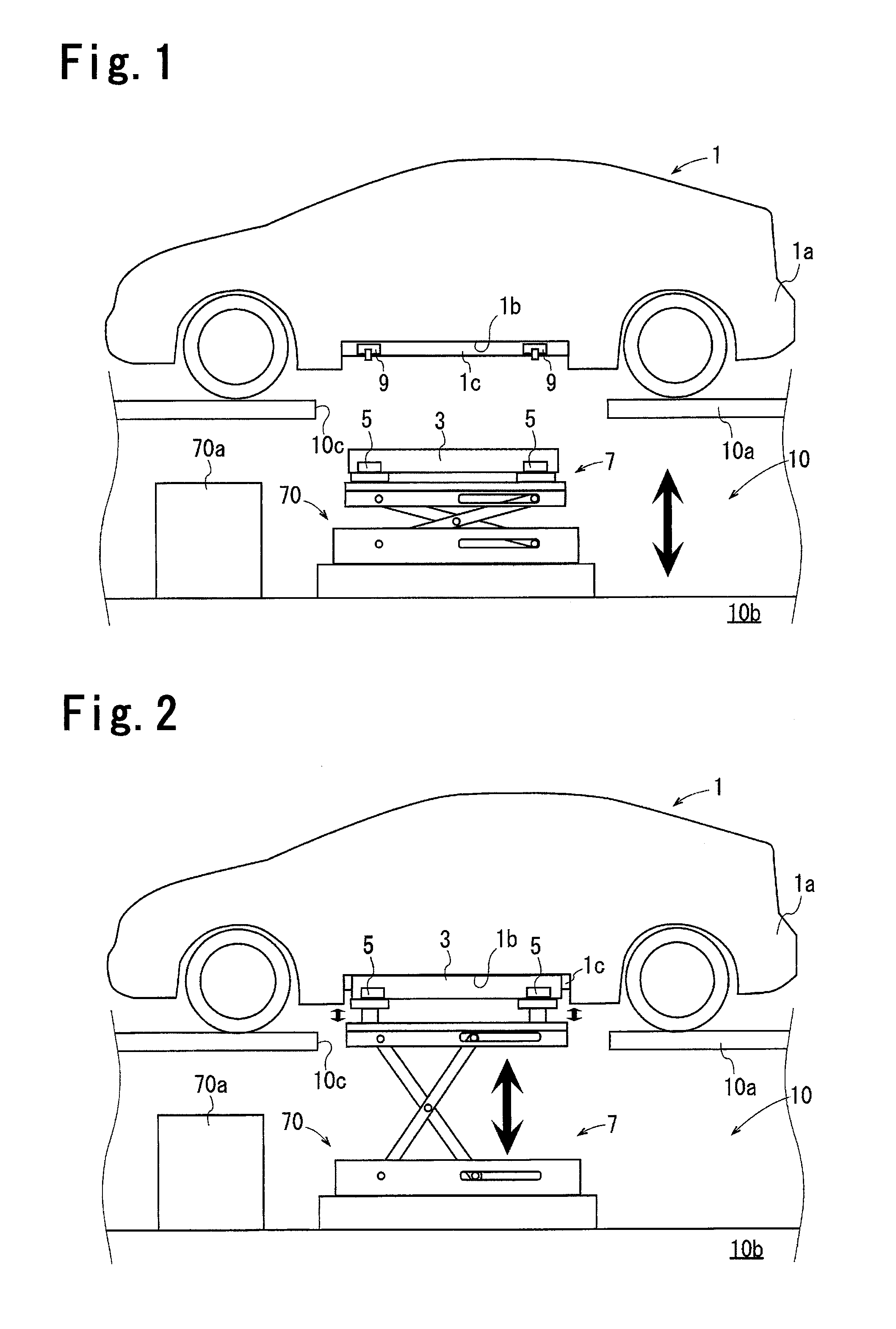
[0047]One embodiment of the present invention will now be described with reference to the drawings. As shown in FIGS. 1 and 2, in the present embodiment, a conveying apparatus 7 attaches and removes a battery unit 3 to and from a vehicle body 1a of an electric vehicle 1 at a battery exchange station 10 (hereinafter referred to as the station 10).

[0048]The station 10 includes an upper floor 10a and a lower floor 10b, which is located under the upper floor 10a. The upper floor 10a includes a communication port 10c, which is in communication with the lower floor 10b. An electric vehicle 1 can be parked on the upper floor 10a.

[0049]The electric vehicle 1 includes a vehicle body 1a. A lower part of the vehicle body 1a includes a mounting cavity 1b, which receives the battery unit 3. The vehicle body la includes two frames 1c, which extend in a front to rear direction of the vehicle body 1a and form the two sideward edges of the mounting cavity 1b.

[0050]The conveying apparatus 7 lifts t...


PUM


Abstract

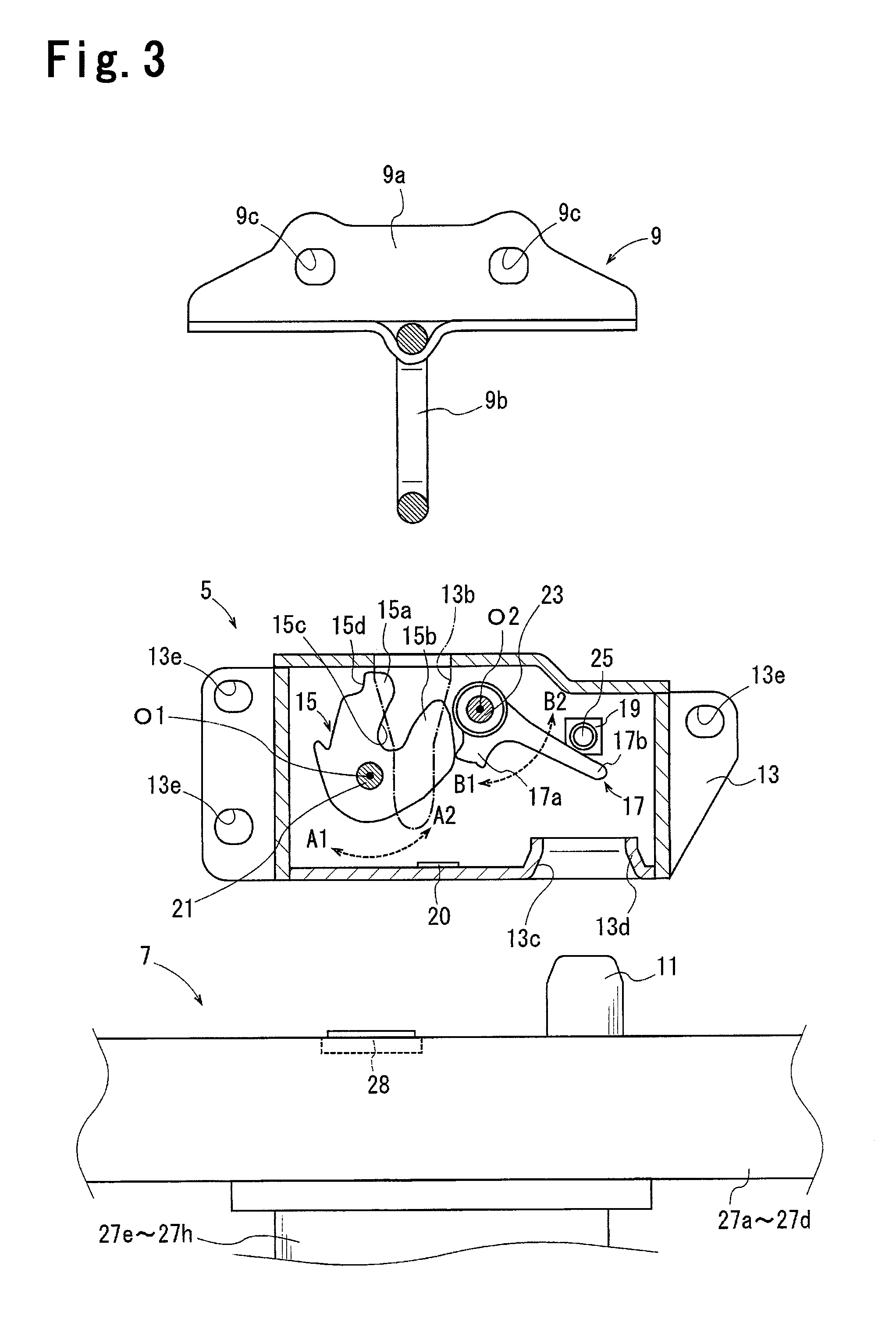
A conveying apparatus is configured to attach a battery unit to a vehicle body at an attachment position by engaging at least three first fastening portions, which are arranged in the vehicle body, respectively with at least three corresponding second fastening portions, which are arranged in the battery unit. The conveying apparatus includes at least three mounts, at least three individual lifting mechanisms, and an individual control unit. The second fastening portions are respectively mounted on the mounts. The individual lifting mechanisms individually lift the mounts to raise the battery unit to the attachment position. The individual control unit is configured to individually control the individual lifting mechanisms.

Description

BACKGROUND OF THE INVENTION[0001]The present invention relates to a conveying apparatus for attaching a battery unit to a vehicle body of an electric vehicle or the like.[0002]Japanese Laid-Open Utility Model Publication No. 54-36727 discloses a lifting apparatus (corresponding to conveying apparatus) that lifts a battery to a predetermined attachment position with respect to a vehicle body to attach the battery to the vehicle body. The lifting apparatus includes four lifting supports, a power transmission mechanism, and a single motor. A battery can be placed on the lifting supports. The power transmission mechanism includes a clutch. The motor lifts all of the lifting supports with the power transmission mechanism. In Japanese Laid-Open Utility Model Publication No. 54-36727, a battery hook is arranged at the lower side of the vehicle body. The battery is attached to the battery hook.[0003]To lift the lifting supports and attach the battery to the vehicle body with the lifting app...

Claims


Application Information

Patent Timeline
Patent Type & Authority Applications(United States)
IPC IPC(8): B66F11/00
CPCB60K1/04B60S5/06Y02T90/124B60K2001/0472B60K2001/0438Y02T90/12
Inventor OJIMA, YOSHIOFUKAGAWA, TAKAHIROMURASE, TAKASHIMOTOYA, AKIHIKOMAKI, HIDEYUKI
Owner TOYOTA IND CORP
Learn More