
Cleaning apparatus for cleaning priniting machine rotary cylinders

Inactive Publication Date: 2012-12-20
FAPPIANO CHRISTIAN +1
View PDF6 Cites 5 Cited by
  • Summary
  • Abstract
  • Description
  • Claims
  • Application Information

AI Technical Summary

Benefits of technology

[0019]Yet another object of the present invention is to provide such a cleaning apparatus adapted to greatly reduce the printing cylinder washing cost and which may be made starting from easily available elements and materials.
[0020]Yet another object of the present invention is to provide such a cleaning apparatus which, owing to its specifically designed features, is very reliable and safe in operation.

Problems solved by technology

Such a total cost depend on the paper material weight and coil height, solvent substances, and is always a very high one.

Method used


Image

  • Cleaning apparatus for cleaning priniting machine rotary cylinders
  • Cleaning apparatus for cleaning priniting machine rotary cylinders
  • Cleaning apparatus for cleaning priniting machine rotary cylinders

Examples


Embodiment Construction

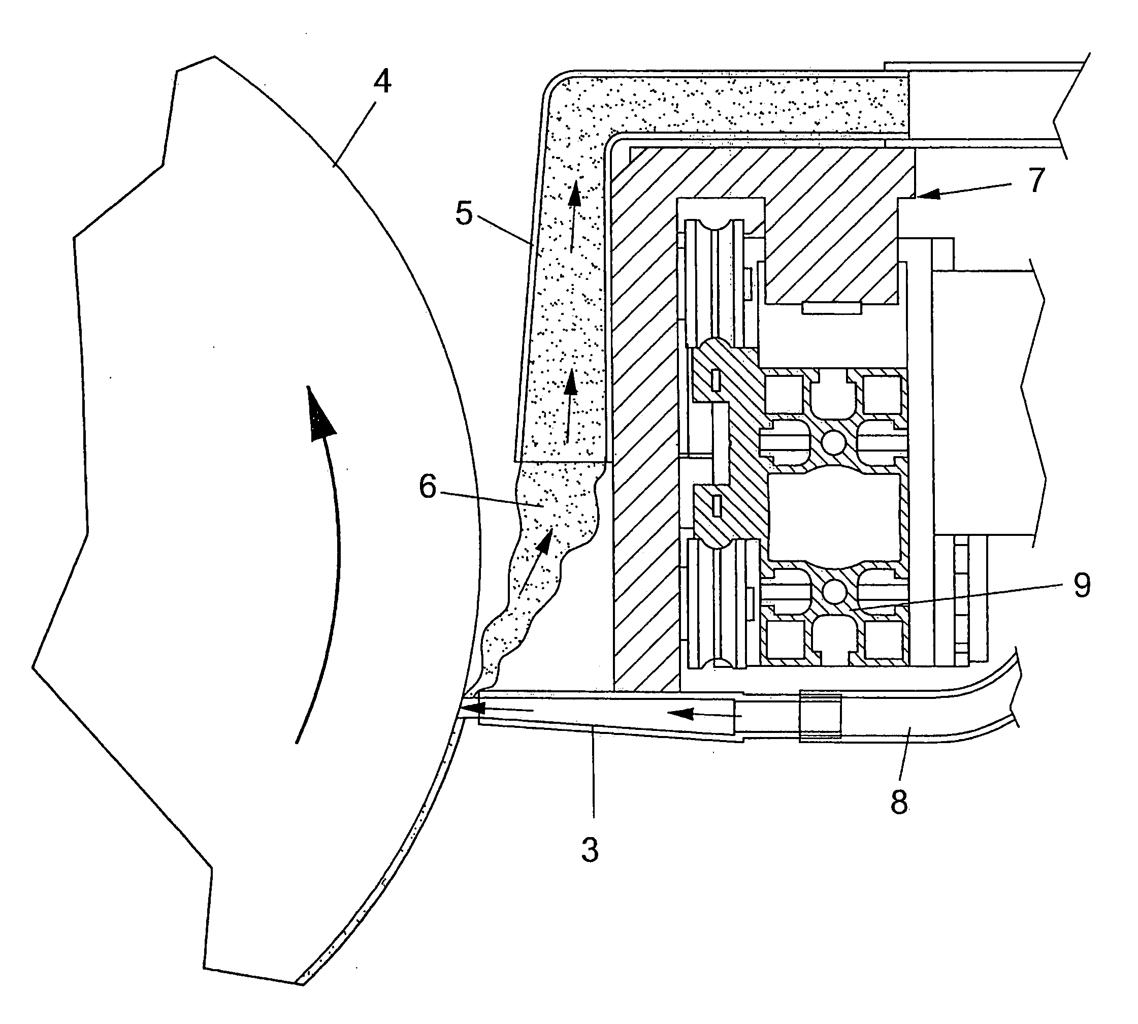
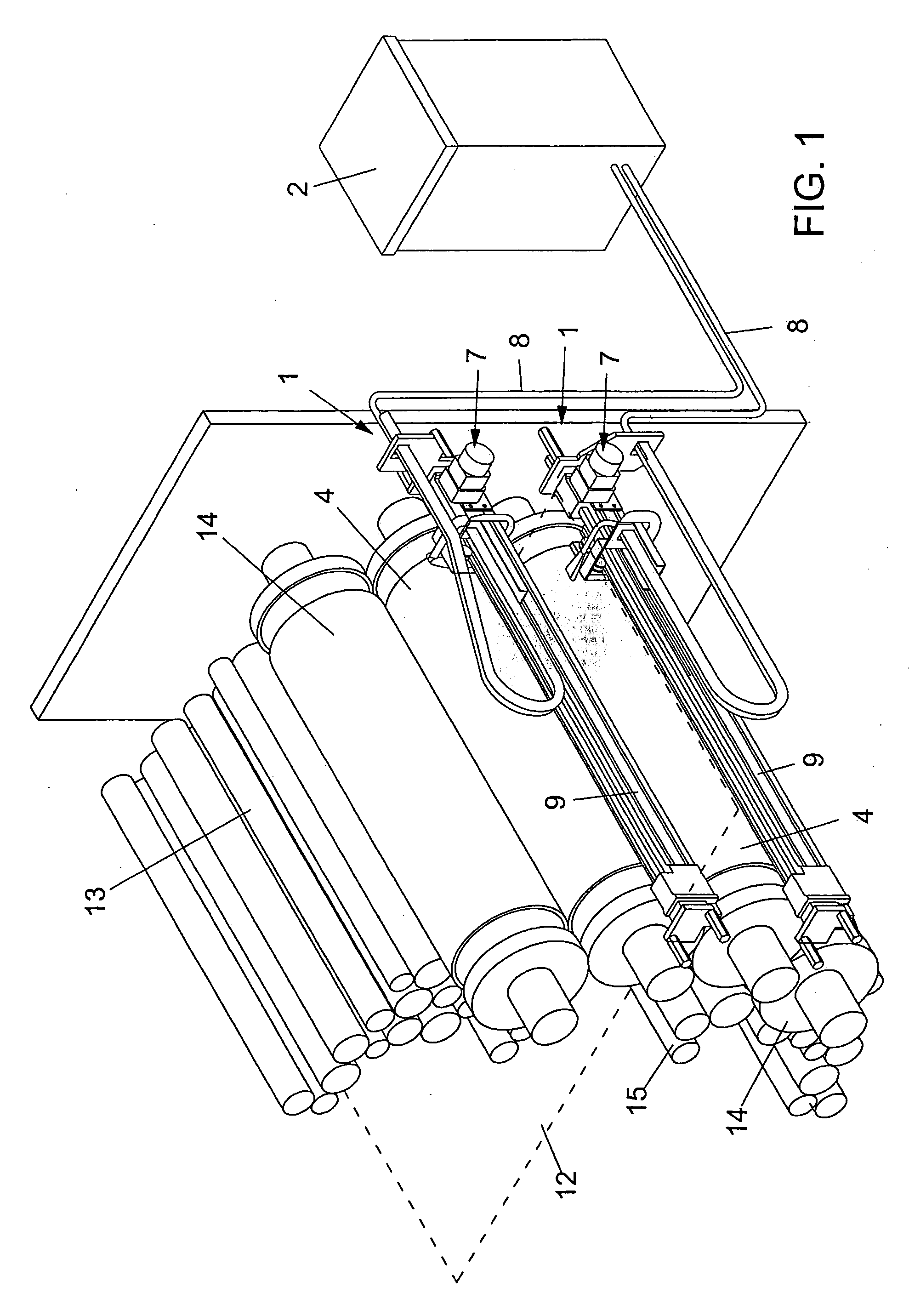
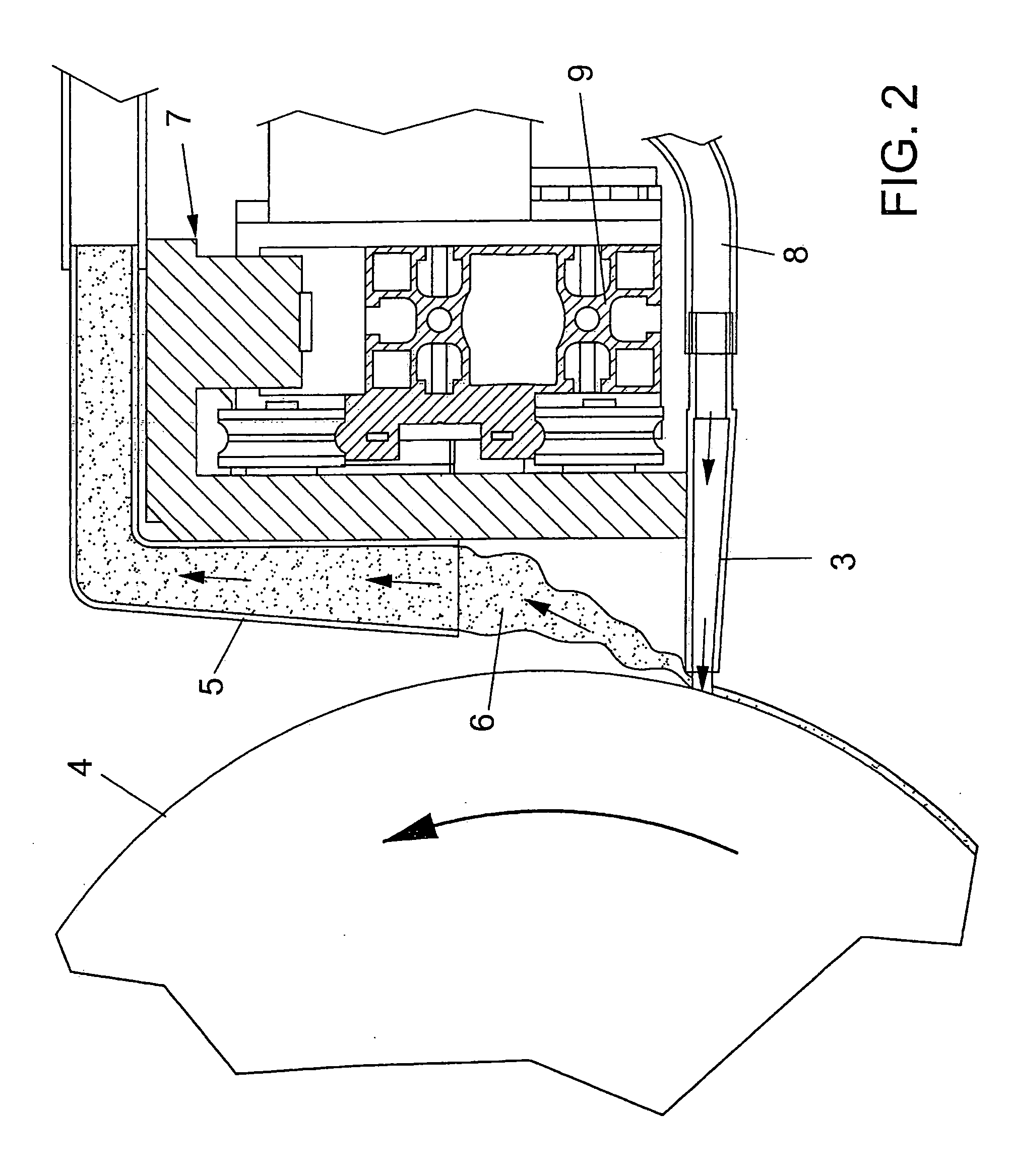
[0031]With reference to the number references of the above mentioned figures, the cleaning apparatus for cleaning printing machine rotary cylinder according to the present invention, which has been indicated generally by the reference number 1, comprises a hopper / delivery device 2 supplying a cleaning material to nozzle means 3 for spraying said cleaning material on a printing cylinder 4 to be cleaned.

[0032]The inventive apparatus further comprises suction means 5 for sucking the material 6 which has been used for cleaning purposes.

[0033]According to the present invention, the apparatus further comprises guide means allowing to displace said nozzle and suction means along a cylinder directrix line to perform a cleaning operation through the overall extension of said cylinder.

[0034]Said cleaning material is preferably a cryogenic cleaning material, for example constituted by CO2 pellets.

[0035]More specifically, said hopper or delivery device 2 supplies the nozzle means through supply...


PUM

PropertyMeasurementUnit
Temperatureaaaaaaaaaa

Abstract

A cleaning apparatus for cleaning printing machines rotary cylinders, characterized in that said cleaning apparatus comprises a delivery device providing a cleaning material to nozzle means for spraying said cleaning material on a cylinder to be cleaned, said cleaning apparatus further comprising suction means for sucking the used cleaning material and guide means allowing to displace said nozzle and suction means along a cylinder directrix line to perform a cleaning operation through the overall extension of said cylinder.

Description

BACKGROUND OF THE INVENTION[0001]The present invention relates to a cleaning apparatus for cleaning printing machine rotary cylinders.[0002]As it is known, a printing machine, for example an offset printing machine, comprises a plurality of printing units each of which includes one or more printing cylinders.[0003]More specifically, a printing rotary machine conventionally comprises four or more printing turrets each of which includes two printing cylinders, coated by a rubber material, which perform a printing operation on the two faces of a paper strip.[0004]Said prior printing rotary machine, accordingly, comprises at least eight rubber coated cylinders, each of which must be periodically cleaned, usually after a half hour working period.[0005]At present, said printing cylinders are cleaned or washed by automatically operated washing bars being applied to each of the printing cylinder to be cleaned.[0006]A prior washing system for washing a rubber material coated printing cylinde...

Claims


Application Information

Patent Timeline
IPC IPC(8): B41F35/02
CPCB24C1/003B41P2235/26B41F35/06B41F35/00
Inventor FAPPIANO, CHRISTIANFAPPIANO, LUIGI
Owner FAPPIANO CHRISTIAN
Learn More