
Lane sensing through lane marker identification for lane centering/keeping

a technology of lane centering and lane marker, which is applied in the direction of steering initiation, instruments, vessel construction, etc., can solve the problems of laborious computational and laborious translation between image size and real world length/distan

Inactive Publication Date: 2012-12-13
GM GLOBAL TECH OPERATIONS LLC
View PDF9 Cites 39 Cited by
  • Summary
  • Abstract
  • Description
  • Claims
  • Application Information

AI Technical Summary

Problems solved by technology

However, this calibration and translation between image size and real world length / distance is labor and computationally intensive.

Method used

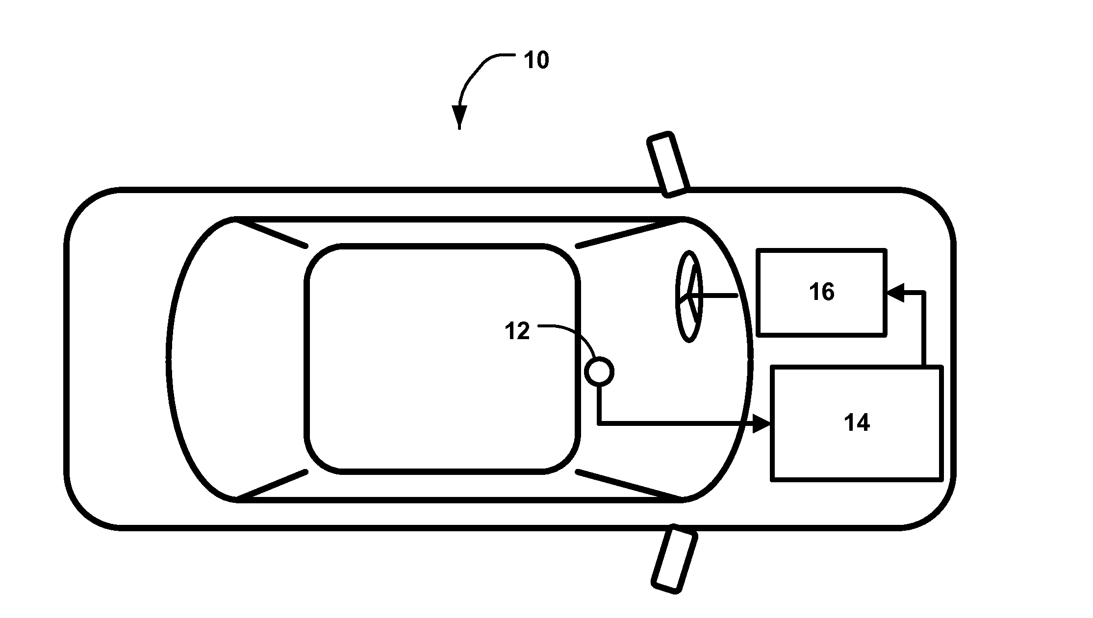
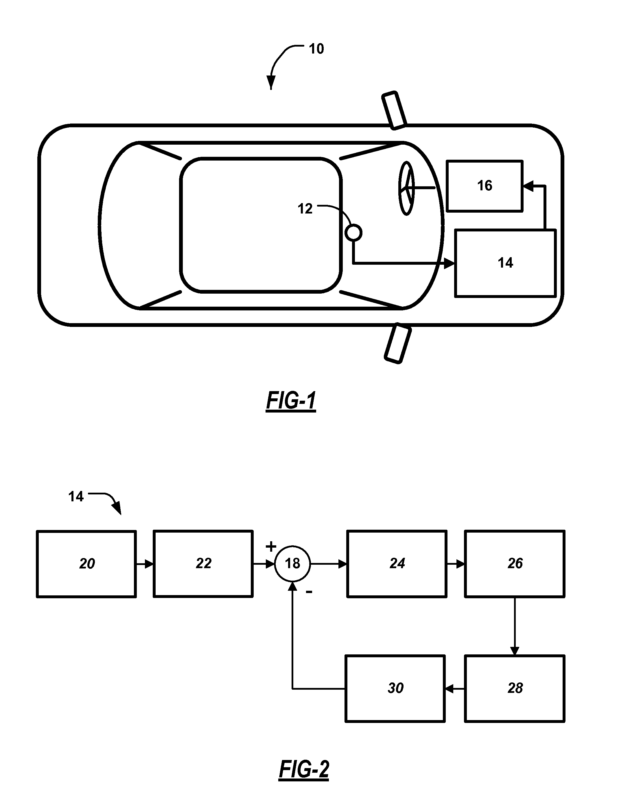
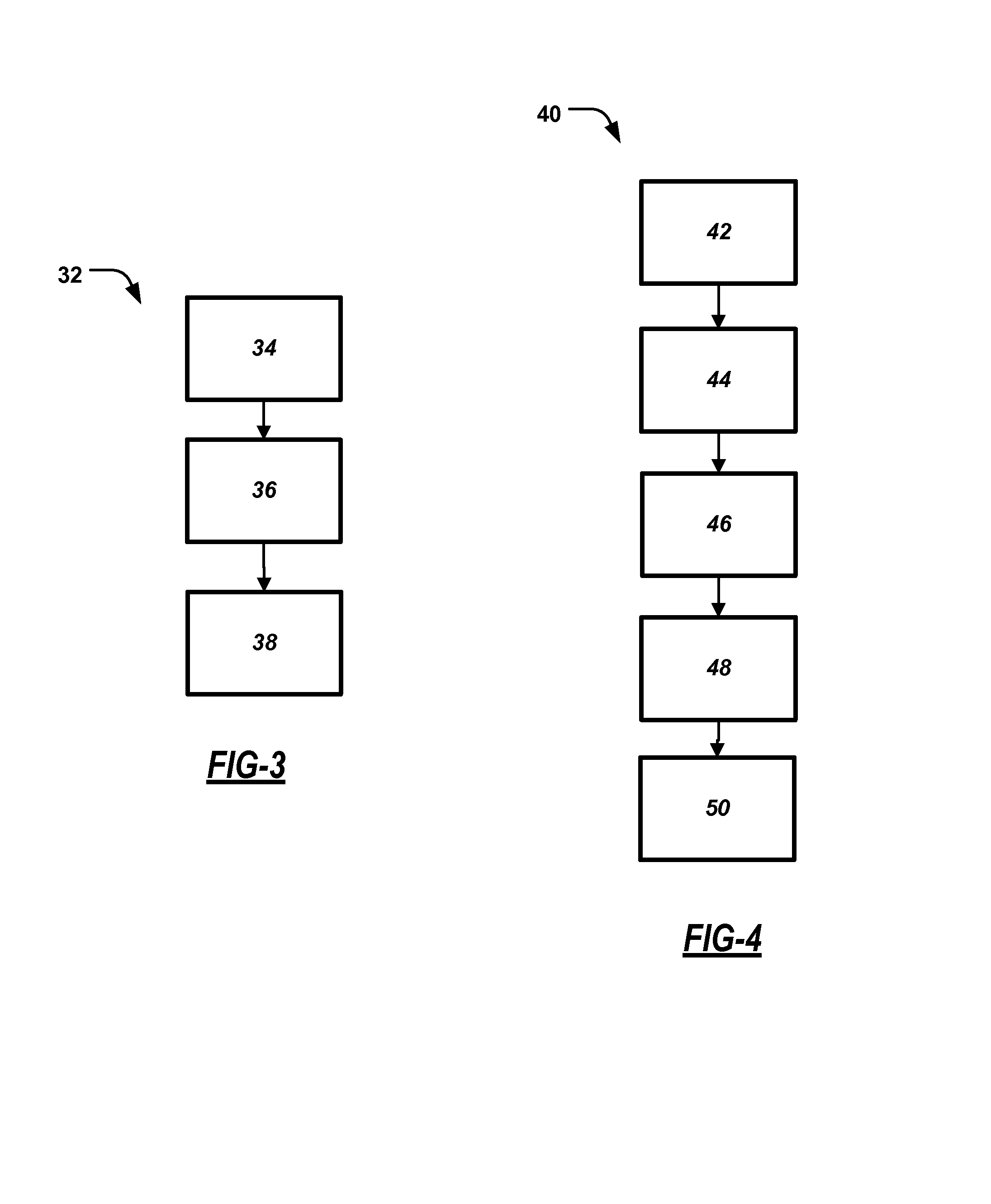

Image

  • Lane sensing through lane marker identification for lane centering/keeping
  • Lane sensing through lane marker identification for lane centering/keeping
  • Lane sensing through lane marker identification for lane centering/keeping

Examples


third embodiment

[0020]The lane centering system 14 can derive the reference lane-center line from a reference image or a set of reference images representing the geometric center of the lane. There are at least three different sources of reference image / images that can represent the geometric center of the lane. For example, in one embodiment an image is provided when the vehicle was in the geometric center of the lane. In another embodiment, multiple images are provided when the vehicle was in the geometric center of the lane. In a third embodiment, images are identified by machine learning techniques as images taken when the vehicle was in the geometric center of the lane.

fourth embodiment

[0021]The lane centering system 14 can derive the reference lane-center line from a reference image or a set of reference images representing the geometric center of the lane plus a bias. There are at least four additional sources of reference image / images that can represent the geometric center of the lane plus a bias. For example, in one embodiment, an image is provided when the vehicle was in the geometric center of the lane plus a bias. In another embodiment, multiple images are provided when the vehicle was in the geometric center of the lane plus some bias. In another embodiment, images are identified by machine learning techniques of a driver's preferred bias (habitual offset) from the geometric center of the lane. In fourth embodiment, images represent an average or typical driver's preference.

[0022]The lane centering system 14 can also base the reference lane-center line on a series of lane-center parameters. The lane-center parameters are derived from a series of images an...


PUM


Abstract

A method for adjusting a vehicle's position in a roadway lane. A camera mounted on the vehicle generates a current image of the lane and the method identifies a current lane-center line in the current image. A reference image is generated and the method identifies a reference lane-center line in the reference image. The method then calculates an error between the current lane-center line and the reference lane-center line and provide steering commands to adjust the position of the vehicle so that the error is reduced.

Description

BACKGROUND OF THE INVENTION[0001]1. Field of the Invention[0002]This invention relates generally to a system and method for detecting the position of a vehicle in a roadway lane and centering the vehicle in the lane and, more particularly, to a system and method for detecting the position of a vehicle in a roadway lane and centering the vehicle in the lane by identifying lane markers from a video sequence of the lane and providing steering control for lane centering.[0003]2. Discussion of the Related Art[0004]The operation of modern vehicles is becoming more autonomous, i.e., vehicles are able to provide driving control with less driver intervention. Cruise control systems have been on vehicles for a number of years where the vehicle operator can set a particular speed of the vehicle, and the vehicle will maintain that speed without the driver operating the throttle. Adaptive cruise control systems have been recently developed in the art where not only does the system maintain the s...

Claims


Application Information

Patent Timeline
IPC IPC(8): B62D6/00
CPCB60W10/20B60W30/12B60W40/06B60W2720/14B60W2710/202B60W2710/207B60W2420/42B60W2420/403
Inventor ZHANG, WENDELITKOUHI, BAKHTIAR BRIANLEE, JIN-WOO
Owner GM GLOBAL TECH OPERATIONS LLC
Learn More