Transmission drive unit

a technology of transmission drive and drive shaft, which is applied in the direction of couplings, manufacturing tools, gearing, etc., can solve the problems of restricting the transmission torque of the drive shaft, and achieve the effect of being particularly reliable and absorbing relatively high radial forces

Inactive Publication Date: 2012-12-06
ROBERT BOSCH GMBH
View PDF5 Cites 4 Cited by
  • Summary
  • Abstract
  • Description
  • Claims
  • Application Information

AI Technical Summary

Benefits of technology

[0002]Proceeding from the prior art described, the invention is based on the object of developing a transmission drive unit in such a manner that it permits good bearing properties and the possibility of transmitting relatively high torques while being able to be produced economically. This object is achieved with a transmission drive unit according to the invention. The invention is based on the concept of using the output element at the same time as a bearing element in order to improve the bearing properties. Since the output element is composed of metal, there is therefore the possibility of designing a metal / plastics bearing which is distinguished by improved wear resistance in comparison to a plastics / plastics bearing.
[0005]In an alternative refinement of the invention, the transmission drive unit can be produced particularly cost-effectively, wherein at the same time relatively high torques can likewise be transmitted. In this case, the invention is based on the concept of enabling the output element to be produced particularly simply and inexpensively by means of an output element which can be connected to the adaptor element and is designed as a deep drawn part.
[0007]As an alternative, provision is made for the adaptor element to be formed by at least partial insert molding of the output element. Such a formation permits a particularly intimate connection between the adaptor element and the output element, thus enabling particularly high torques to be transmitted.

Problems solved by technology

Furthermore, force is introduced by the adaptor element to the output element over a relatively small axial length, and therefore the driving torque which can be transmitted is restricted.

Method used


Image

  • Transmission drive unit
  • Transmission drive unit
  • Transmission drive unit

Examples


Embodiment Construction

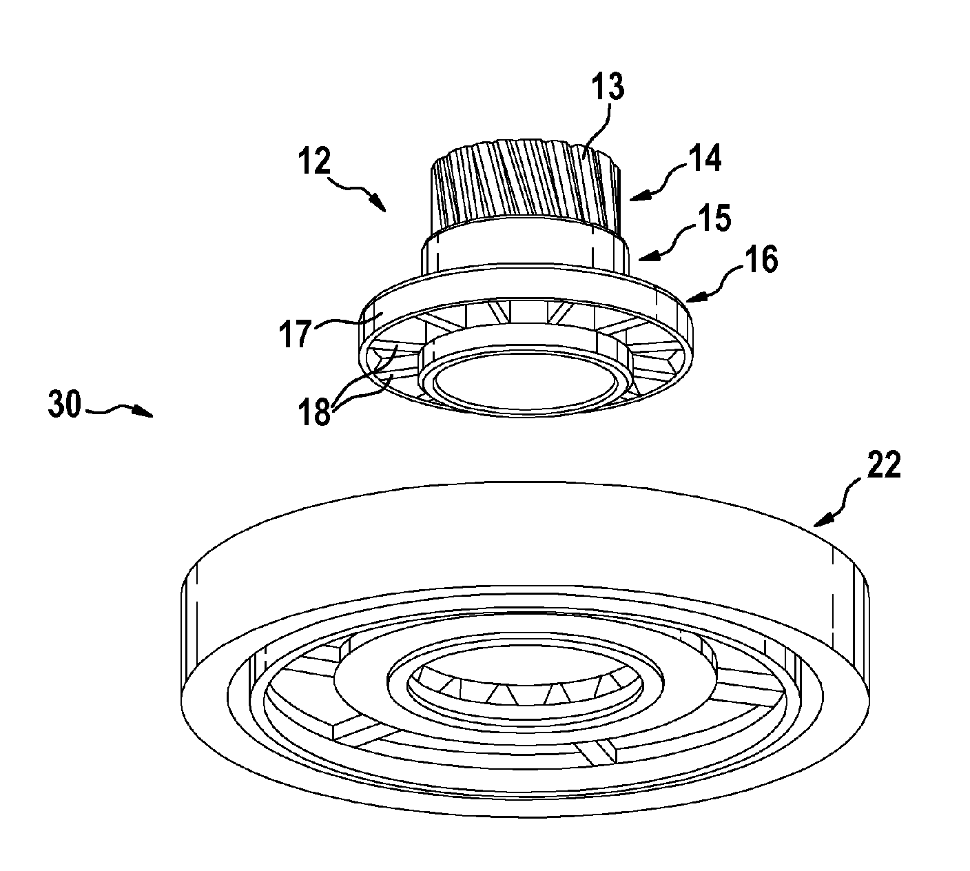
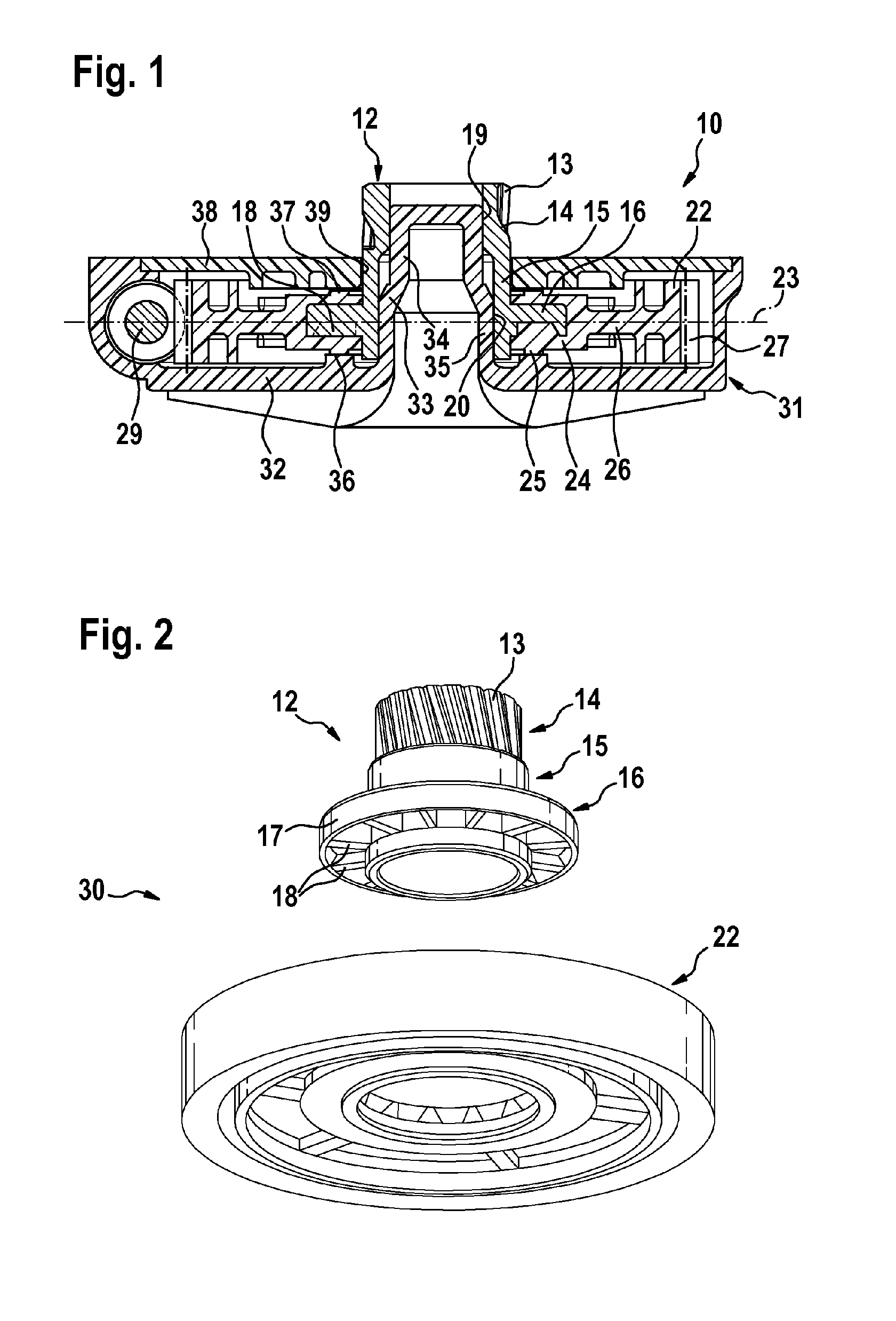
[0027]FIG. 1 illustrates a first transmission drive unit 10, as provided in particular, but not restrictively, for use in a sliding roof drive of a motor vehicle. The transmission drive unit 10 has an output element which is composed of metal, in particular of sintered metal, and is designed as an output pinion 12. In this case, the output pinion 12 constitutes the intersection with a sliding roof system which is in engagement with a transmission means (not illustrated) via an oblique external toothing 13 formed on the output pinion 12. The adjustment of the roof mechanism is realized via the transmission means.

[0028]According to FIG. 2, the output pinion 12 has three sections 14 to 16. The external toothing 13 is formed on the first section 14. A second section 15, which is of substantially sleeve-shaped design, adjoins the first section 14. The second section 15 is surrounded approximately centrally by an annular third region 16 which has an encircling, web-like edge 17. Molded ri...


PUM

PropertyMeasurementUnit
Symmetryaaaaaaaaaa

Abstract

The invention relates to a transmission drive unit (10; 40; 50; 70) having an adapter element made of plastic (22; 22a; 53; 73) via which a torque is initiated by an input element (29) and a drive element (12; 12a; 51; 72) made of metal for forwarding the torque, wherein the adapter element (22; 22a; 53; 73) and the drive element (12; 12a; 51; 72) are directly coupled to one another and rigidly connected, wherein the adapter element (22; 22a; 53; 73) is an injection molded part which is formed by at least partial overmolding of the drive element (12; 12a; 51; 72) and wherein the drive element (12; 12a; 51; 72) serves as a bearing element.

Description

BACKGROUND OF THE INVENTION[0001]The invention relates to a transmission drive unit. The applicant's subsequent publication DE 10 2009 000 760 A1 discloses a transmission drive unit which has an output element which is produced from metal, in particular from sintered metal, and is at least partially insert molded by an adaptor element designed as a worm wheel. The adaptor element is accommodated within a transmission housing. The adaptor element is mounted rotatably on an axle stub of the housing base, wherein both the axle stub and the adaptor element are composed of plastic. The previously known transmission drive unit which is designed in particular as a sliding roof drive can be produced relatively inexpensively by the adaptor element being injection molded on. The wear resistance of the known transmission drive unit is worthy of improvement in particular under high loads. Furthermore, force is introduced by the adaptor element to the output element over a relatively small axial...

Claims


Application Information

Patent Timeline
IPC IPC(8): F16D1/027B29C45/14F16H57/021
CPCF16H1/16F16H55/06Y10T403/475F16H57/021F16H2055/065F16H55/22Y10T74/19828Y10T74/19921B60J7/02
Inventor ALBRECHT, SUSANNEBRAUNEGGER, FRANKHEITZ, ROBERTSTEUER, PETERREICHMANN, SIEGFRIED
Owner ROBERT BOSCH GMBH
Why Eureka
Try Eureka