
Wear amount measuring device, wear amount measuring method, wear amount measuring program and storage medium

a technology of wear amount and measurement method, which is applied in the direction of measurement devices, static indicating devices, instruments, etc., can solve the problems of pitch skipping, uneven wear of surface hardened layer, and difficulty in accurately measuring the wear amount, so as to accurately compare the wear amount measurement target, accurately compute the amount, and accurately measure

Active Publication Date: 2012-12-06
KOMATSU LTD
View PDF0 Cites 20 Cited by
  • Summary
  • Abstract
  • Description
  • Claims
  • Application Information

AI Technical Summary

Benefits of technology

[0028]The present invention has been produced in view of the aforementioned drawbacks. It is an object of the present invention to provide a wear amount measuring device, a wear amount measuring method, a wear amount measuring program and a storage medium whereby the wear amount can be accurately measured even in measuring the wear amount of a measurement target that progression of wear varies from position to position.
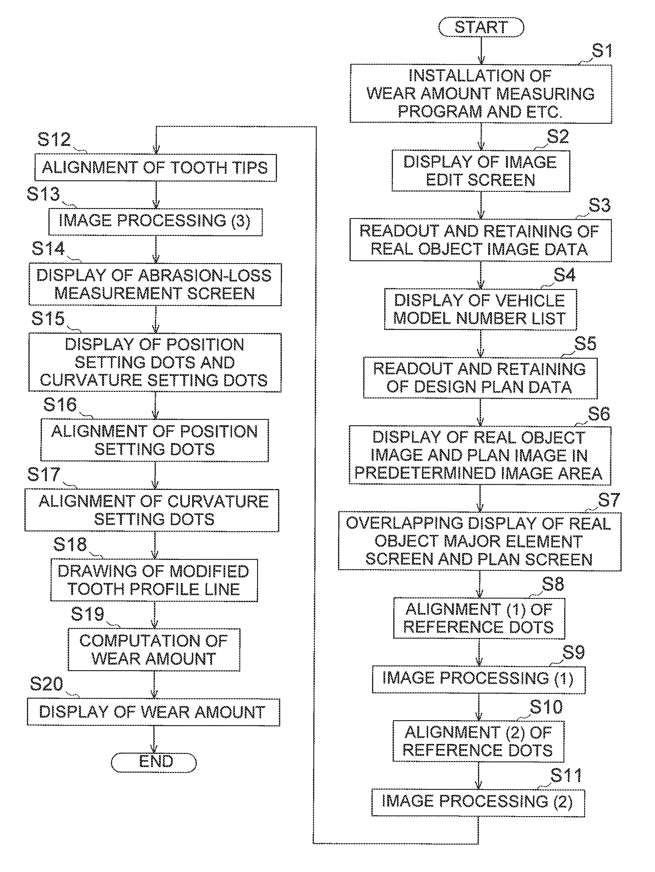
[0036]In the present invention, the real object image and the plan image are overlapped at an equal scale while the reference parts thereof are matched. Accordingly, it is possible to accurately compare the wear amount measurement target in the real object image and that in the plan. image. Further, the wear amount is computed based on the magnitude of the interval between the measurement contour line drawn along the contour of the wear amount measurement target in the real object image and the plan contour line in the plan image. Accordingly, it is possible to accurately compute how much and which part of the wear amount measurement target is worn away. Therefore, the wear amount can be accurately measured even in measuring the wear amount of a measurement target that progression of wear varies from position to position.

Problems solved by technology

However, the surface hardened layer is worn away in proportion to the cumulative time of the travelling action of the work vehicle.
After the surface hardened layer is entirely scraped due to wear, wear of the tooth portions of the sprocket wheel is rapidly progressed and this may cause pitch skipping and etc.
Accordingly, troubles may be caused in the work and the travelling action of the work vehicle.
The work of transferring the tooth portions of the actual sprocket wheel onto the transparent film (Procedure (1)) is bothersome.
Therefore, accuracy in transference (Procedure (1)) varies because of difference in techniques of operators and etc. it is thus difficult to reliably guarantee certain reliability.
Further, decision of replacement timing based on the operator's visual inspection inevitably varies.
On the other hand, in a sprocket wheel embedded in a track-type drive unit for a hydraulic excavator, for instance, wear is differently progressed between the tooth bottom and the tooth tip, and thus, wear of the sprocket wheel is not necessarily uniformly progressed along the circumferential direction.
Therefore, the wheel inspection device described in Japan Laid-open Patent Application Publication No, JP-A-H05-52536 has a drawback that the wear amount cannot be accurately measured when a measurement target of the wear amount is an object that wear is differently progressed from position to position.
However, these devices cannot directly measure the wear amount.

Method used


Image

  • Wear amount measuring device, wear amount measuring method, wear amount measuring program and storage medium
  • Wear amount measuring device, wear amount measuring method, wear amount measuring program and storage medium
  • Wear amount measuring device, wear amount measuring method, wear amount measuring program and storage medium

Examples


Embodiment Construction

[0049]A wear amount measuring device, a wear amount measuring method, a wear amount measuring program and a storage medium according to an exemplary embodiment of the present invention will be hereinafter explained with reference to the drawings.

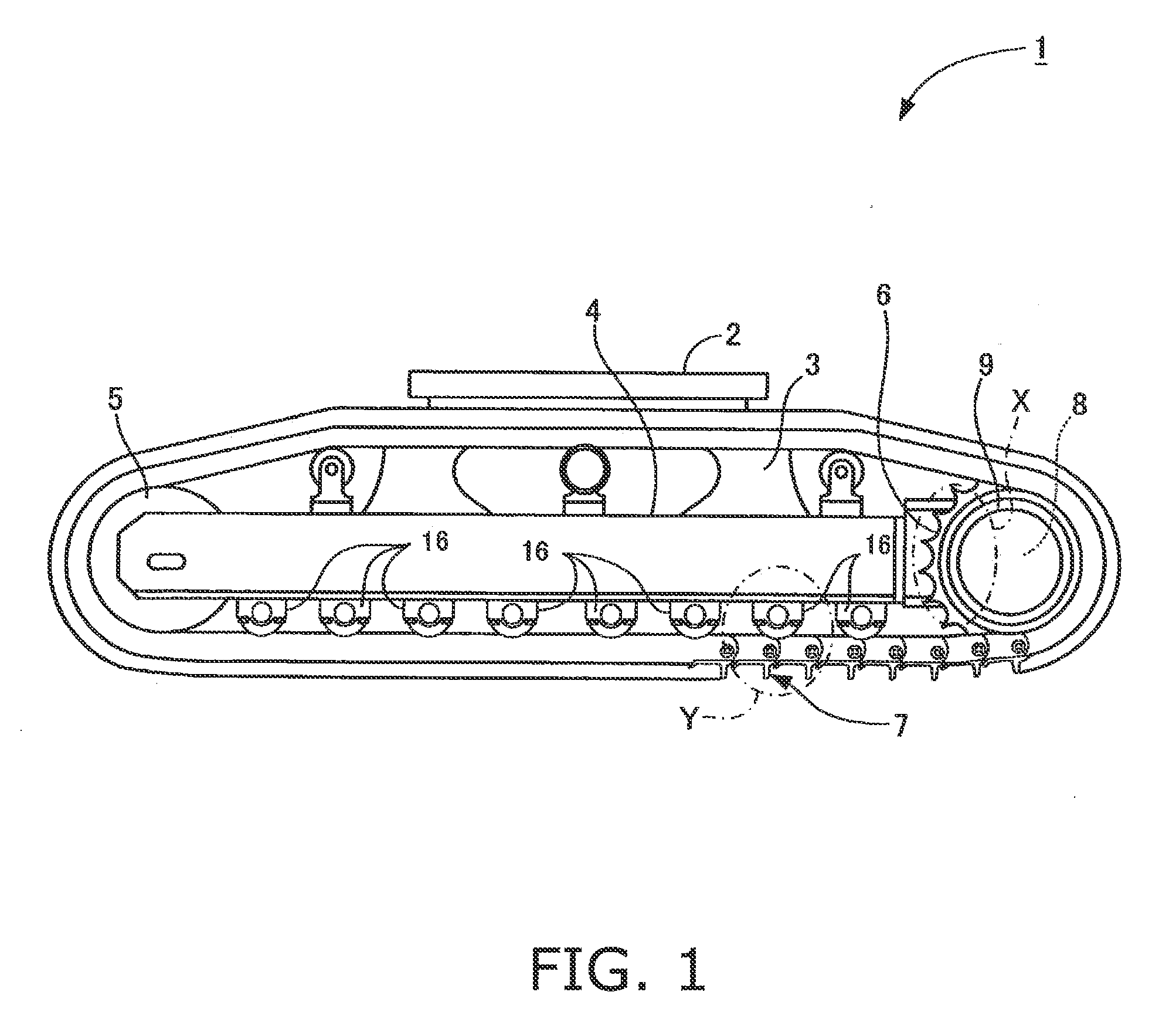
[0050]it should be noted that the present exemplary embodiment is explained with an exemplary case of applying the present invention to a wear amount measuring device intended for a sprocket wheel, as a wear amount measurement target, embedded in a track-type drive unit of a hydraulic excavator as a work vehicle. However, the application target of the present invention is not limited to the above. The present invention can be applied to a wear amount measuring device intended for the other expendable part as a wear amount measurement target.

Schematic Explanation of Track-Type Drive Unit 1 of Hydraulic Excavator

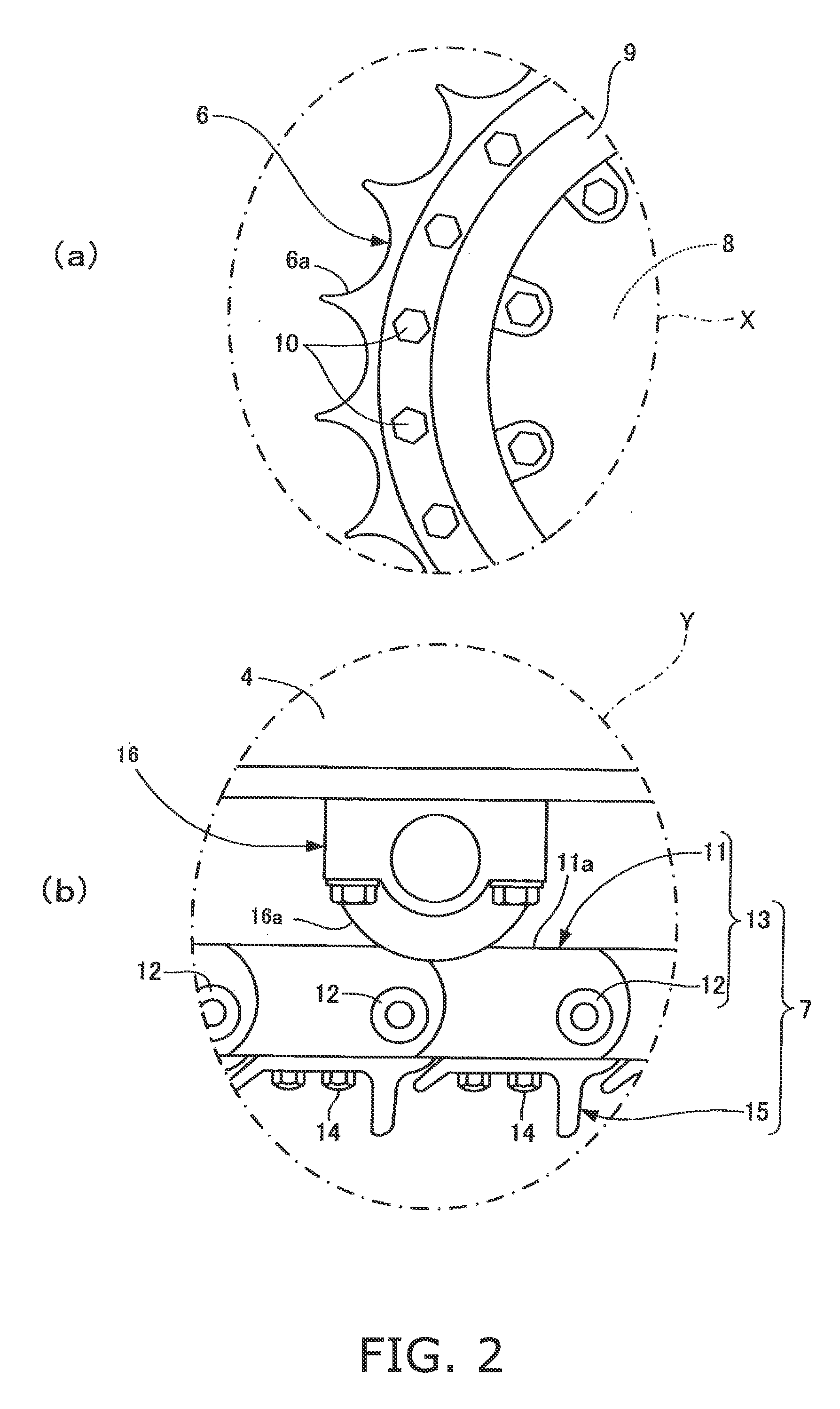
[0051]A track-type drive unit 1 illustrated in FIG. 1 includes a pair of track frames 4 (only left-side one is illustrated) respectiv...


PUM


Abstract

A wear amount measuring device includes an image display unit, an image processing unit, and a wear amount computing unit. The image display unit displays a real object image based on real object image data containing a wear amount measurement target and a reference part, and displays a plan image based on design plan data containing the wear amount measurement target and the reference part. The image processing unit executes an image processing of overlapping the real object image and the plan image at an equal scale on a corresponding positional relation when the reference parts are matched. The wear amount computing unit computes a wear amount based on a magnitude of an interval between a measurement contour line drawn along a contour of the wear amount measurement target in the real object image and a plan contour line in the plan image.

Description

CROSS-REFERENCE TO RELATED APPLICATIONS[0001]This application claims priority to Japanese Patent Application No. 2010-027146, filed on Feb. 10, 2010, the disclosure of which is hereby incorporated herein by reference in its entirety.TECHNICAL FIELD[0002]The present invention relates to a wear amount measuring device, a wear amount measuring method, a wear amount measuring program and a storage medium for measuring the wear amount of an expendable part such as a sprocket wheel embedded in a track-type drive unit of a work vehicle such as a hydraulic excavator or a bulldozer.BACKGROUND ART[0003]Track-type drive units fire work vehicles such as hydraulic excavators, bulldozers and etc. include an idler tumbler (front idler), a sprocket wheel (driving wheel) and a crawler belt attached and stretched over the idler tumbler and the sprocket wheel in an oval shape (see e.g., Japan Laid-open Patent Application Publication No. JP-A-2003-285781). The travelling actions of the work vehicles ar...

Claims


Application Information

Patent Timeline
IPC IPC(8): G09G5/377
CPCG01B21/20G01B11/24
Inventor MARUMOTO, SHIGETOWAKAI, HIDEYUKISUZAKI, YUKIHIROITOU, DAIJIROUTSUBAKI, TOMOYUKIHISAMATSU, KENICHI
Owner KOMATSU LTD
Learn More