However, in the case of an automatic faucet, the opening of the front end side of the water spout pipe is in a position which is not viewed by a user, and thus there is a problem that where the water is discharged from is not understood by the user, and it is difficult to use the faucet.
Thus, expansion of the water
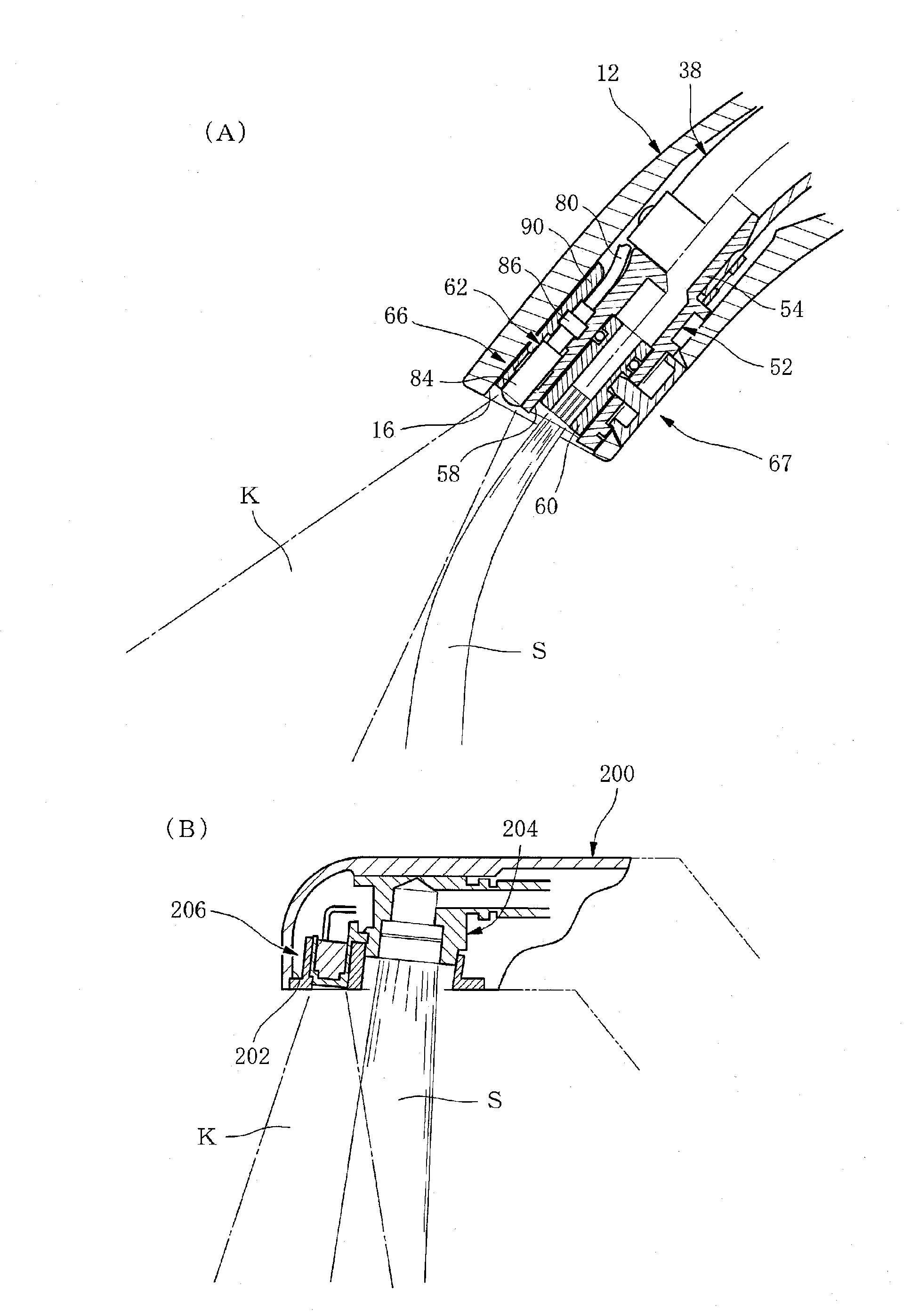
stream of the discharged water (the spouted water) is easily superimposed on the detection area of the sensor, and there is a risk of the sensor erroneously detecting the water
stream as the detection target.
In addition, since the sensor faces downward, there is a risk of erroneously detecting a basin surface such as a wash basin positioned on the lower side as the detection target.
At the same time, the sensor may erroneously detect the water
stream discharged from the water spout member as the detection target.
Further, since the water spout member is projected forward than the sensor, there is a problem in that, when cleaning a sensor window, the water spout member to be is disturbed, and thus the cleaning is difficult.
In addition, since the water spout member is projected from the opening of the tip face of the water spout pipe, there is a problem in that the water spout member is seen from a user and causes a user to feel a sense of cumbersome.
However, in the automatic faucet, since the water spout member is projected forward and is positioned with respect to the sensor, the cleaning is also difficult when cleaning the sensor window.
In addition, there is a problem in that, if the detection area of the sensor is not narrowly limited, the sensor may erroneously detect the water stream discharged from the water spout member.
However, as disclosed in
Patent Literature 4 and
Patent Literature 2, in the case of the automatic faucet provided with the light emitting element, the light receiving element, and the sensor including the sensor circuit in the tip section of the water spout pipe, a shape of the tip section of the water spout pipe has been inevitably increased, and there is a problem in that the size of the overall water spout pipe along with this, and the design is degraded.
In this case, there is a risk that the sensor erroneously detects the discharged water from the automatic faucet, and even when a user does not hold out his hand, water is continuously discharged.
Specifically, in a case where the light emitting section and the light receiving section, that is the light emitting window on the light emitting side and the light receiving window on the light receiving side are installed near the water spout member by constituting the light emitting section and the light receiving section in the tip section of the
optical fiber, the erroneous detection is easily generated.
However, the opening face of the tip of the water spout is not installed to be tube-axially inserted from the opening intersecting with the pipe axis in the state where the detection sensor and the water spout member are held on the holding member.
However, as disclosed in
Patent Literature 4 and Patent Literature 2, in the case of the automatic faucet provided with the light emitting element, the light receiving element, and the sensor including the sensor circuit in the tip section of the water spout pipe, a shape of the tip section of the water spout pipe has been inevitably increased, and there is a problem in that the entire water spout pipe is increased along with this, and the design is degraded.
However, regardless whether or not the light emitting section and the light receiving section in the sensor are configured in the light emitting element, the light receiving element, or the tip section of the
optical fiber on the light emitting side and the tip section of the
optical fiber on the light receiving side, in the related art, the problems as below had been caused when detecting the detection target using the sensor.
As a result, there is a risk that the sensor erroneously detects.
Accordingly, the structure is complicated and the working process is many when assembling.
Accordingly, many times are consumed in the maintenance work.
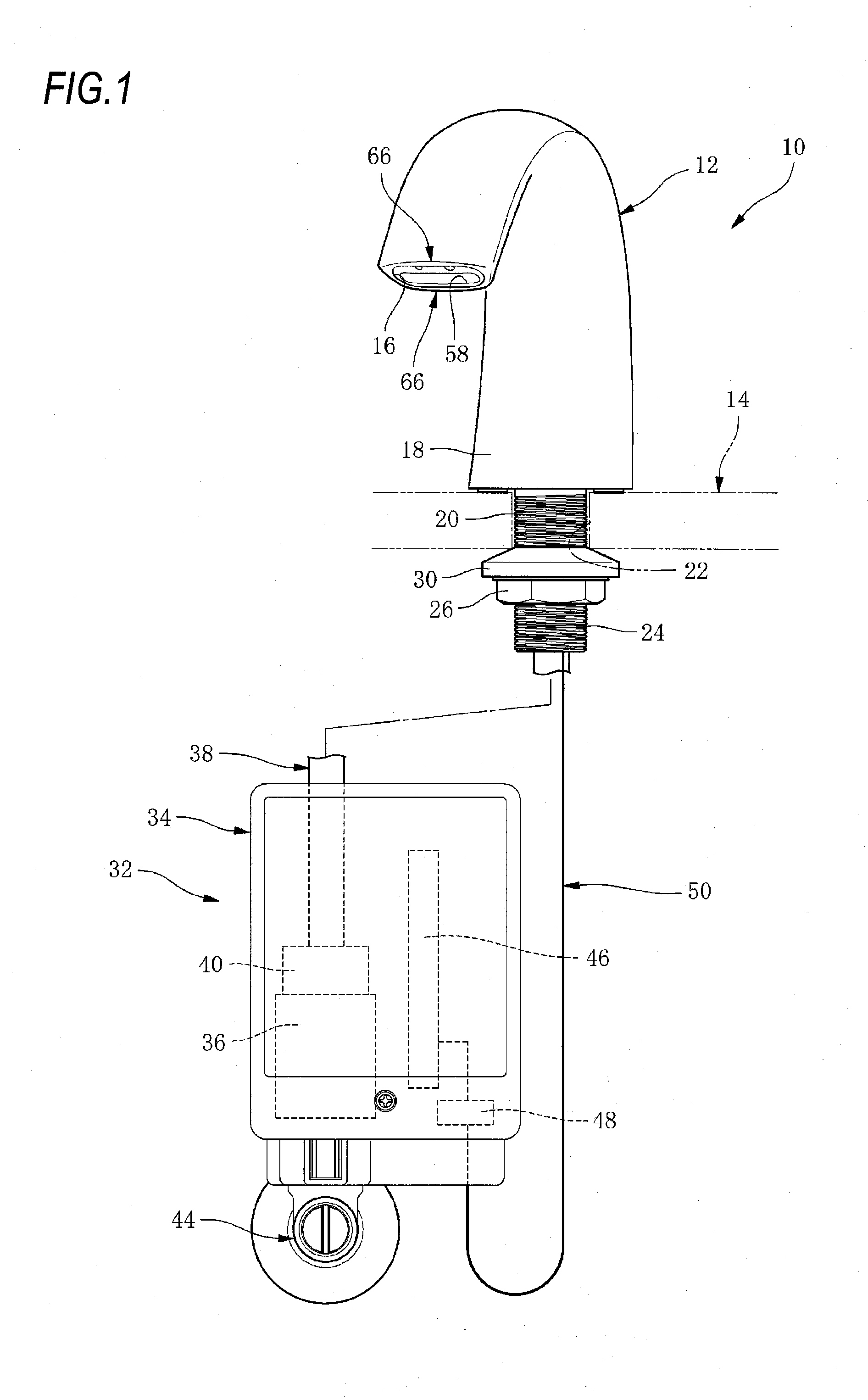
Although the cases of the automatic faucet have been described as above, the problems are commonly generated in the water discharging device which includes the discharging end member and the water spout member in the tip section of the water spout pipe.
The problem is also caused in a case of providing the sensor main body including the light emitting element, the light receiving element and the sensor circuit in the tip section of the water spout pipe, as well as a case of providing them in the water spout pipe in other locations.
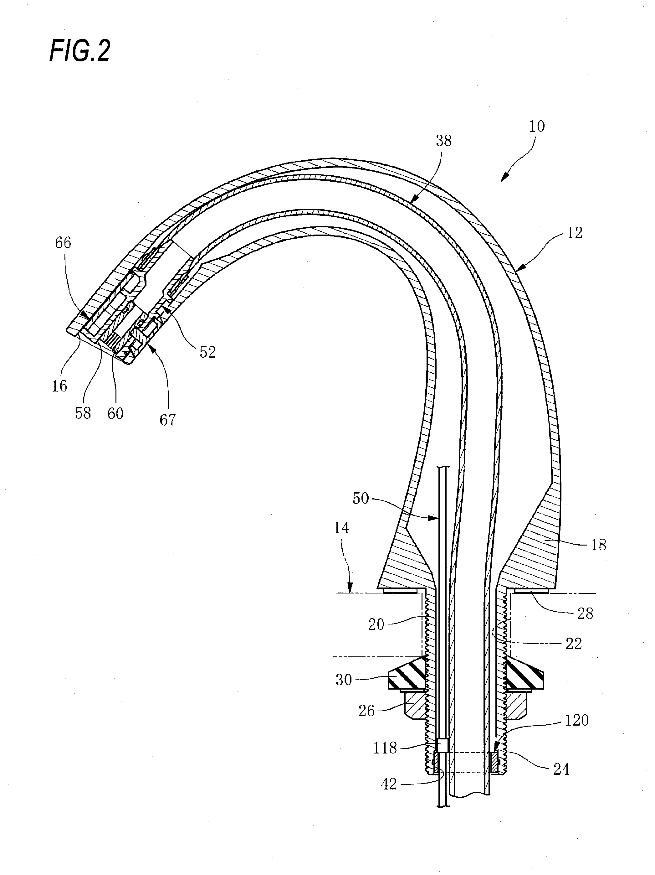
However, in such a case, as specifically described in Patent Literature 8, the cord of the optical
fiber is exposed at the lower space of the attachment base such as the counter between the water spout pipe and the function section box, and when attaching the faucet and during maintenance work after attaching, during cleaning or the like, the exposed portion of the cord may be erroneously stretched.
In this manner, when the exposed portion of the cord is stretched, the optical
fiber is damaged in the water spout pipe by the tensile force, or the tensile force is applied to the tip section of the optical
fiber attached to the water spout pipe, that is, the light projection section and the light receiving section, and then they may be away from the
normal position or may be damaged, so that the function as the sensor is damaged.
The similar problems are also caused in a case where the sensor main body including the light emitting element, the light receiving element, and the sensor circuit is provided in the tip section of the water spout pipe or the like and the cord of the
electric wire is extended from the sensor main body along the inner portion of the water spout pipe, is also extended from the water spout pipe to the lower space of the attachment base and is connected to the function section box placed in the lower space.
Accordingly, the
electric wire is
cut in the connection section or the sensor main body connected thereto may be damaged.
