
Audio processing system

a processing system and audio technology, applied in the field of audio processing system/apparatus, can solve the problems of complex devices of audio mixing consoles, difficult for operators to correctly associate data output, and more difficult for users to correctly combine information, and achieve the effect of enhancing problem solving capabilities

Active Publication Date: 2012-11-29
HARMAN INT IND INC +1
View PDF10 Cites 12 Cited by
  • Summary
  • Abstract
  • Description
  • Claims
  • Application Information

AI Technical Summary

Benefits of technology

The patent describes an audio processing system that allows users to easily see and combine information about external sources with information about internal settings of the system. This is accomplished through a user interface that allows users to assign inputs to different channels and a control device that controls the display of graphics based on the status of the sources. The system can also display the status of sources in real-time, without requiring a wired connection between the system and the sources. The technical effect of this is that users can more easily understand and solve problems related to external sources, such as battery levels or RF field strength.

Problems solved by technology

Audio mixing consoles may be complex devices which allow a wide variety of signal operations and parameters for the operations to be set by a user.
When such status information of sources is collected by a dedicated external computer and output on a screen of the computer, it may be challenging for the operator to correctly associate data output on the computer with data output via the optical output device of the audio processing apparatus.
This can make it even more challenging for a user to correctly combine information output by the audio processing system with information shown on a separate computer.
In some examples, there may be some sources which do not provide status data to the audio processing apparatus.
Thereby, the risk that the status information may be misunderstood when operating the audio processing apparatus is mitigated.

Method used


Image

  • Audio processing system
  • Audio processing system
  • Audio processing system

Examples


Embodiment Construction

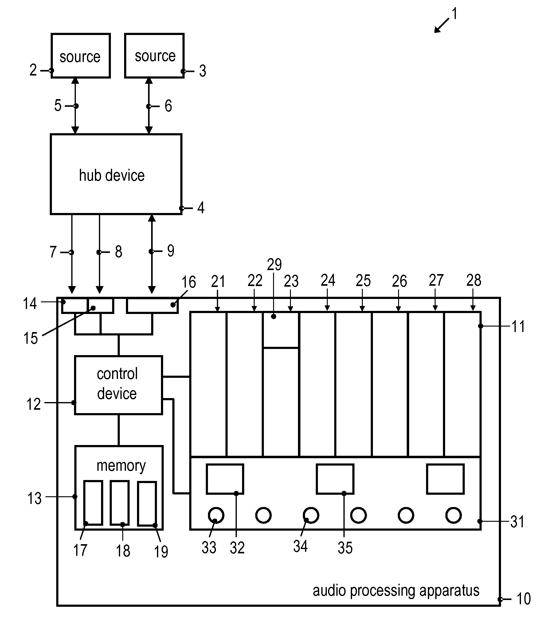
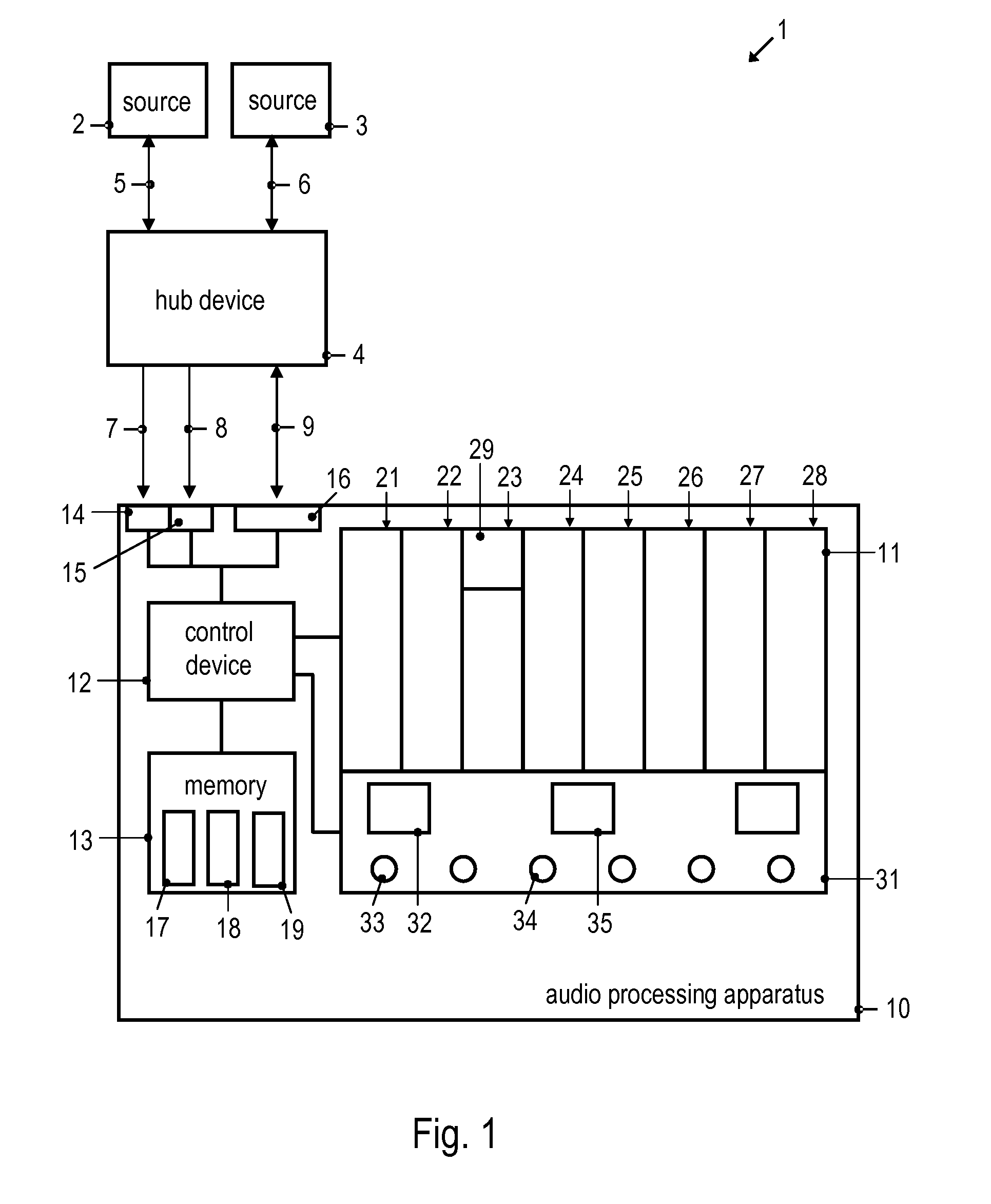
[0046]FIG. 1 is a schematic diagram of an audio system 1. The audio system 1 includes plural sources 2, 3 and an audio processing apparatus 10. The audio processing apparatus 10 may be an audio mixing console, a combined audio / video processing apparatus, a digital audio mixing console, or a similar apparatus or system. Accordingly, as used herein the term “apparatus” may include a standalone device, or a multi-component distributed system, such as an audio processing system. The audio system 1 may also include a hub device 4. The hub device 4 may be used to couple one or several of the sources 2, 3 to the audio processing apparatus 10.

[0047]The audio system 1 may include additional sources (not shown in FIG. 1) which provide audio signals to the audio processing apparatus 10. The additional sources may also be coupled to the audio processing apparatus 10 via the hub device 4. In other implementations, all or some of the sources may be coupled directly to the audio processing apparat...


PUM


Abstract

An audio processing apparatus is configured to process audio signals from a plurality of sources. The audio processing apparatus may include a digital interface to receive status data indicating a status of at least one source, and an optical output device having a plurality of groups of graphics display areas which are respectively assigned to one of a plurality of audio channels of the audio processing apparatus. The audio processing apparatus may also include a control device configured to receive the status data, to determine at least one group of graphics display areas based on the received status data, and to control a graphics display area of the determined at least one group to display graphics generated based on the received status data.

Description

1. PRIORITY CLAIM[0001]This application claims the benefit of priority from European Patent Application No. 11 160 535.8, filed Mar. 30, 2011, which is incorporated by reference.2. TECHNICAL FIELD[0002]The invention relates to an audio processing system / apparatus for processing audio signals from a plurality of sources and a method of outputting status information. Embodiments of the invention relate in particular to such an audio processing system / apparatus which has an optical output device on which graphics can be displayed.3. RELATED ART[0003]Audio processing apparatuses are widely used. Examples include an audio mixing console or a combined audio / video processing apparatus. Such an apparatus generally has inputs for receiving audio signals from plural sources. The sources may be microphones. The audio signals may be processed in plural audio channels and may undergo signal mixing. For illustration, processing techniques that may be applied include filtering, amplification, comb...

Claims


Application Information

Patent Timeline
Patent Type & Authority Applications(United States)
IPC IPC(8): G06T1/00
CPCH04H60/04H04R3/00H04R29/00
Inventor BROWN, ANDYSONNLEITNER, PHILIPPHUBER, ROBERTSORENSEN, BJORNMEIER, DETLEF
Owner HARMAN INT IND INC
Learn More