LED decorative light
- Summary
- Abstract
- Description
- Claims
- Application Information
AI Technical Summary
Benefits of technology
Problems solved by technology
Method used
Image

Examples
embodiment 1
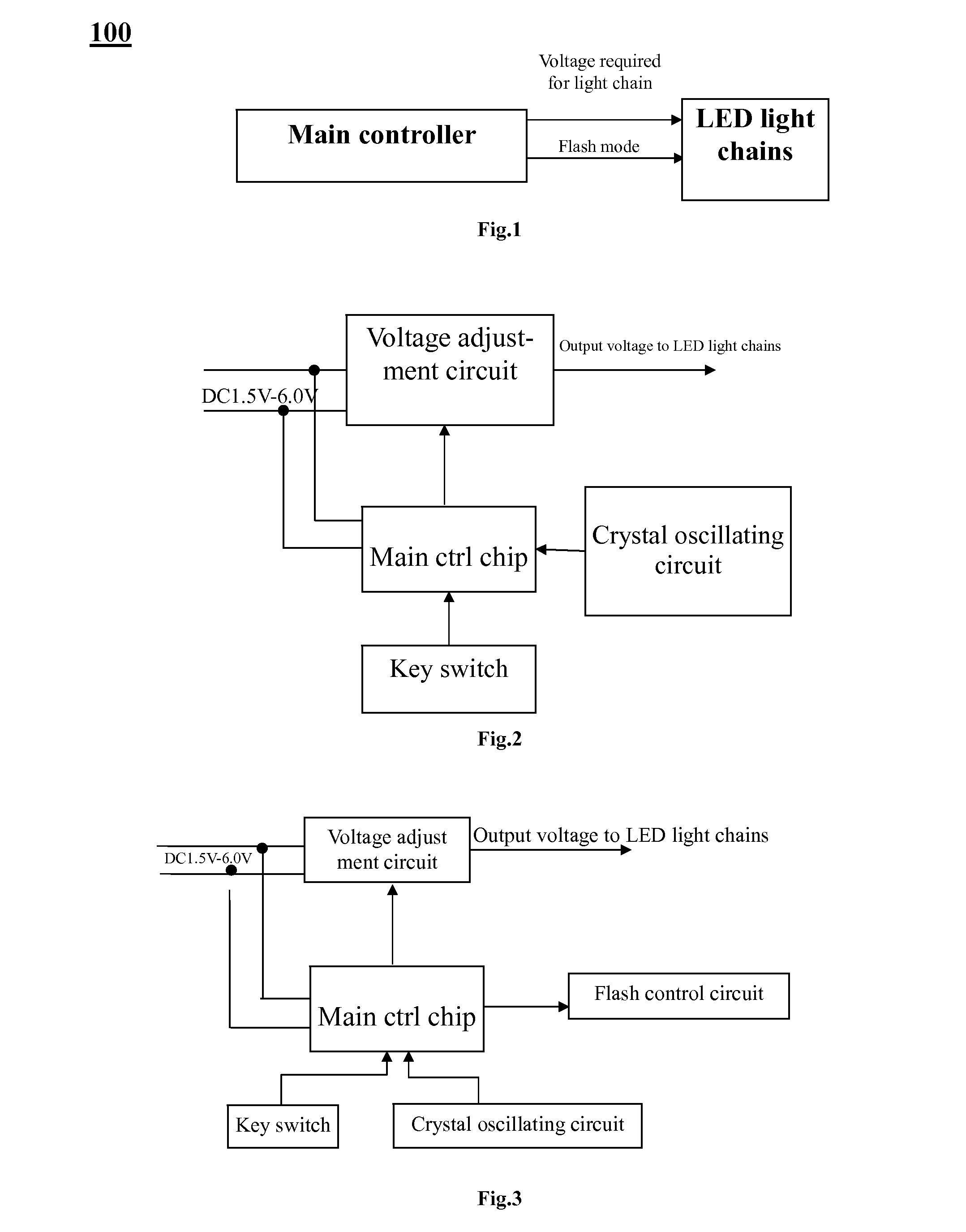
[0036]In structural block diagram of LED decorative light shown in FIG. 1, the LED decorative light consists of main controller and LED light chains.
[0037]In structural block diagram of main controller shown in FIG. 2, the main controller comprises key switch, crystal oscillating circuit, voltage adjustment circuit, and main control chip. The key switch and the crystal oscillating circuit are connected to main control chip respectively. The pulse width modulation end of the main control chip outputs PWM of variable duty ratio. The crystal oscillating circuit is used to provide instruction cycle required for main control chip. The key switch is used to control operating state of main control chip. The voltage adjustment circuit is used to adjust DC power supply voltage to the value required for LED light chains. Of this circuit, the input end is connected to said DC power supply, the control end is connected to main control chip pulse width modulation end, and the output end is conne...
embodiment 2
[0044]This embodiment is basically similar to the above one, with difference that the controller 20 is also provided with a flashing control circuit 17, as shown in FIG. 3. Input end of the flashing control circuit 17 is connected to I / O port of the main control chip and the output end to LED light chains. I / O port of the main control chip outputs PWM and drives LED to flash via the flashing control circuit.
[0045]As shown in FIG. 5, the flashing control circuit 17 comprises a resistor 19 and a triode 21. The resistor is connected to the base of the triode, forming a base driver circuit 18. The resistor 19 is connected to I / O port of the main control chip and collector of the triode 21 is connected to LED light chains 11. The flashing control circuit 17 is provided with two base driver circuits 18, which enables 6-8 flashing functions of the LED light chains.
[0046]In this embodiment, the key switch 3 is also used to send input signal to the main control chip 4 for selecting flashing ...
embodiment 3
[0047]This is another embodiment of the main controller.
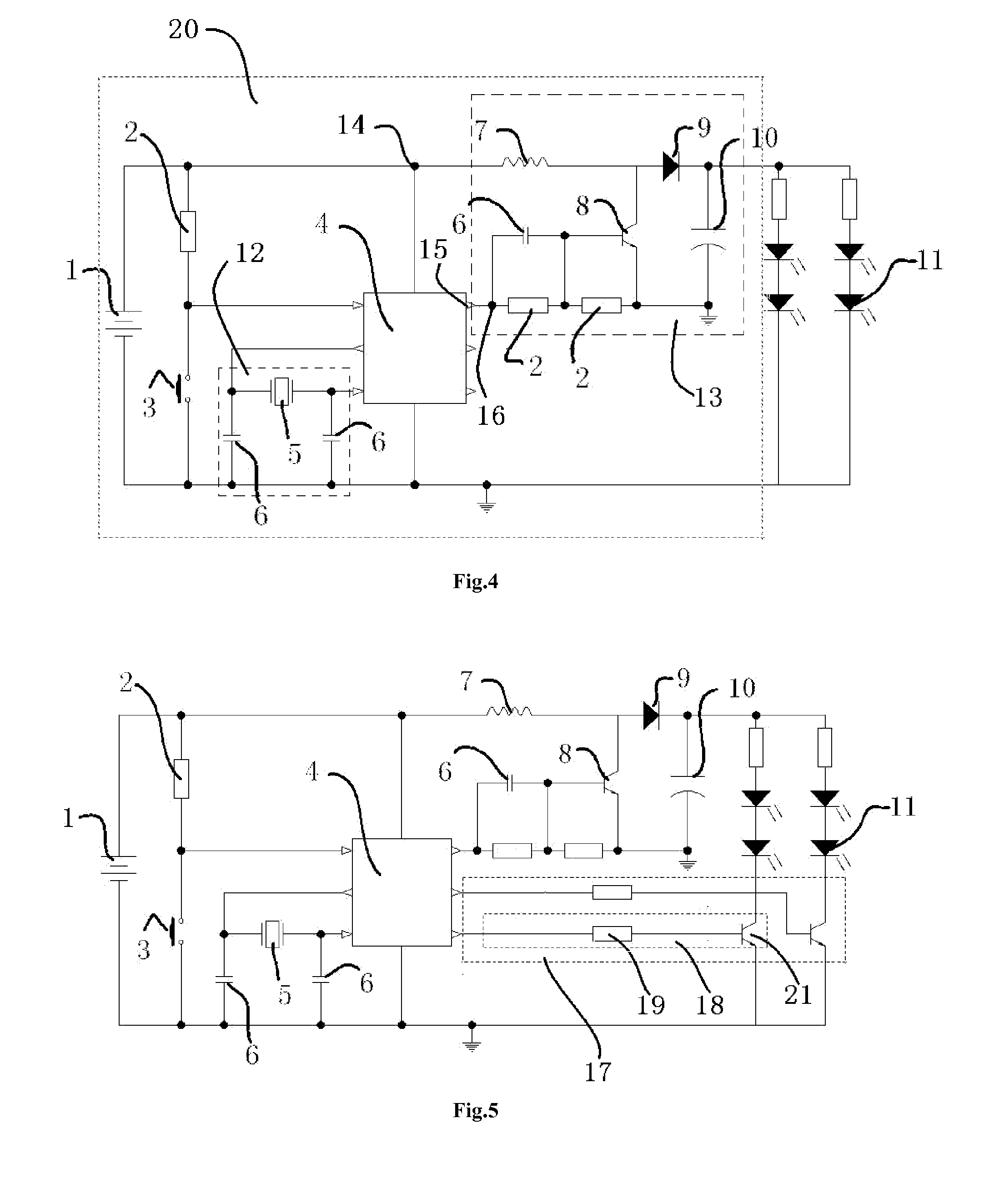
[0048]As shown in FIG. 7, the main controller comprises DC power supply, main control chip, oscillating circuit, voltage adjustment circuit, LED light chains control circuit, sampling circuit, and wireless receiving circuit.
[0049]Of this preferred embodiment, the electric circuit adopted for the LED light chains is shown in FIG. 16. Circuit of each component is described below.
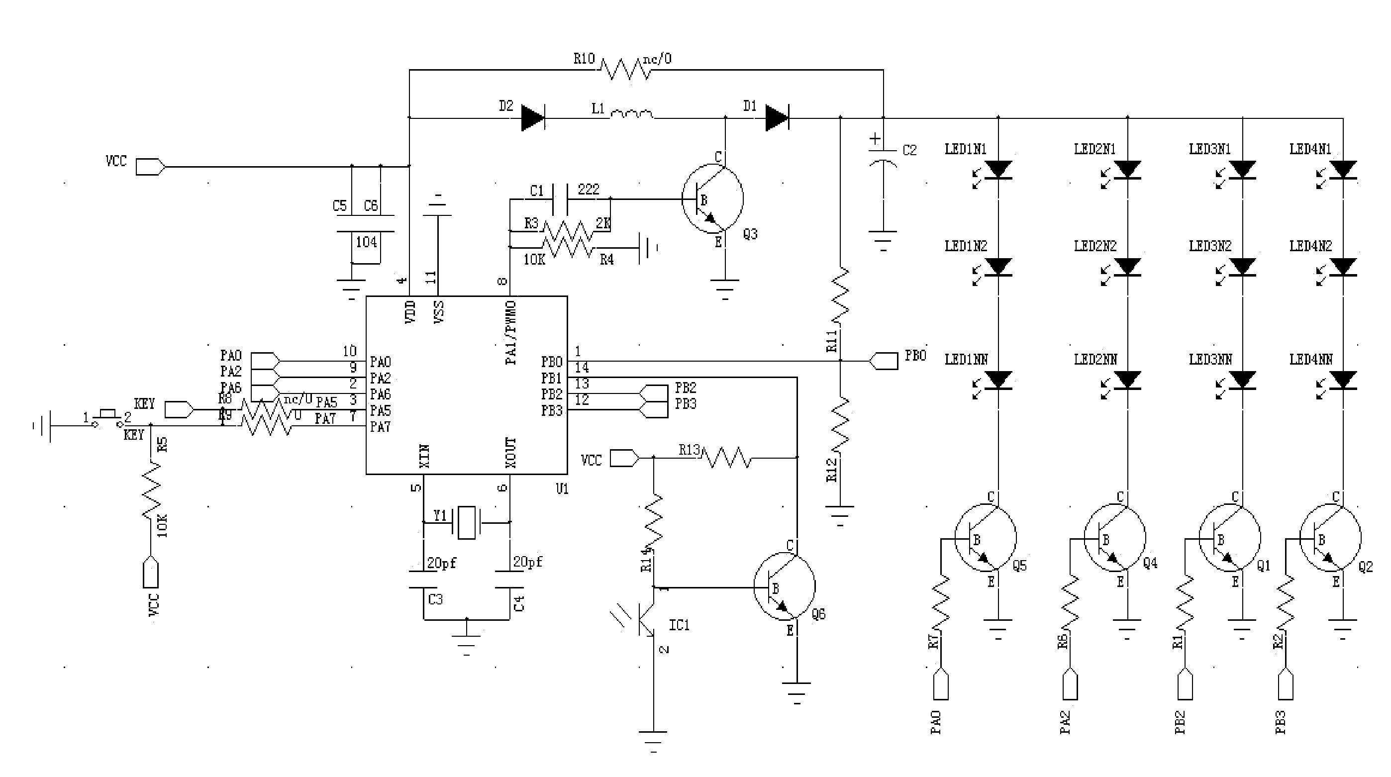
[0050]For the main control chip (SCM) shown in FIG. 8, power supply input end VCC is connected to one end of capacitor C5 and capacitor C6 (to SCM pin 4 VDD). The other end of capacitor C5 and capacitor C6 is connected to earth. SCM pin 7 is connected to one end of resistor R9. The other end of resistor R9 is connected to one end of KEY and one end of resistor R5. The other end of KEY is connected to earth and the other end of resistor R5 is connected to power supply input end VCC. SCM pin 5 XIN is connected to one end of crystal oscillator Y1 and capacit...
PUM
 Abstract
Description
Claims
Application Information
 - R&D
- Intellectual Property
- Life Sciences
- Materials
- Tech Scout
- Unparalleled Data Quality
- Higher Quality Content
- 60% Fewer Hallucinations
Browse by: Latest US Patents, China's latest patents, Technical Efficacy Thesaurus, Application Domain, Technology Topic, Popular Technical Reports.
© 2025 PatSnap. All rights reserved.Legal|Privacy policy|Modern Slavery Act Transparency Statement|Sitemap|About US| Contact US: help@patsnap.com