
Multi-loop adjustable knotless anchor assembly, adjustable capture mechanism, and method for repair

Active Publication Date: 2012-11-22
THAL RAYMOND
View PDF7 Cites 53 Cited by
  • Summary
  • Abstract
  • Description
  • Claims
  • Application Information

AI Technical Summary

Benefits of technology

[0021]It is a further object of the present invention to provide a method for securing tissue wherein the mounting sleeve includes an open proximal end and an open distal end defining a cylindrical passageway and allowing access therethrough. The method further includes the step of passing both the first and second elongated members through the passageway and into the small cavity defined by a bottom of the anchor hole, and orienting the first and second anchors transversely to a longitudinal axis of the cylindrical mounting sleeve to thereby lock the first and second elongated members in position.
[0023]It is another object of the present invention to provide a method for securing tissue further including the step of tensioning either the tissue suture loop or the anchor suture.
[0024]It is a further object of the present invention to provide a method for securing tissue further including the step of tensioning the tissue suture loop.
[0027]It is a further object of the present invention to provide a method for securing tissue further including the step of passing the first elongated member through the passageway and into the small cavity defined by a bottom of the anchor hole, and orienting the first anchor transversely to a longitudinal axis of the cylindrical anchor mounting sleeve to thereby lock the bone anchor in position.

Problems solved by technology

The placement of bone tunnels for repair can be difficult and generally require large open incisions.
The process of passing the anchored suture through the soft tissue and tying a knot is time consuming and difficult to undertake in the tight space encountered during arthroscopic surgery and sometimes even in conventional open surgery.

Method used


Image

  • Multi-loop adjustable knotless anchor assembly, adjustable capture mechanism, and method for repair
  • Multi-loop adjustable knotless anchor assembly, adjustable capture mechanism, and method for repair
  • Multi-loop adjustable knotless anchor assembly, adjustable capture mechanism, and method for repair

Examples


Embodiment Construction

[0040]The detailed embodiments of the present invention are disclosed herein. It should be understood, however, that the disclosed embodiments are merely exemplary of the invention, which may be embodied in various forms. Therefore, the details disclosed herein are not to be interpreted as limiting, but merely as a basis for teaching one skilled in the art how to make and / or use the invention.

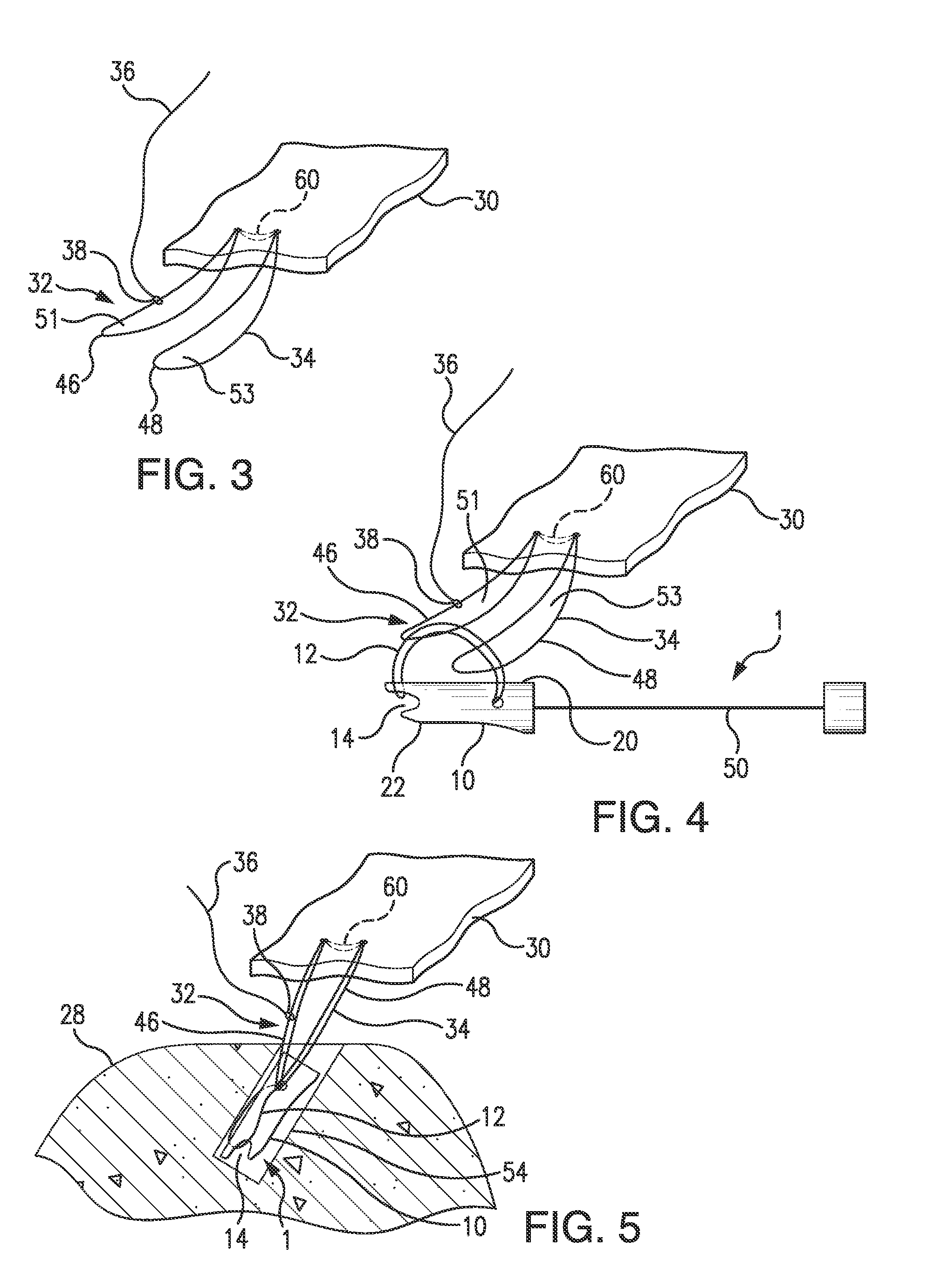
[0041]In accordance with the present invention, and with reference to FIGS. 1 to 6, the present procedure is achieved using existing bone anchors 1, for example, the BIOKNOTLESS™ / LUPINE™ bone anchors of DePuy Mitek as described in U.S. Pat. Nos. 5,709,708 and 5,782,864, which are incorporated by reference, and which are shown in FIGS. 2, 4, 5 and 6.

[0042]Each of the bone anchors 1 preferably employed in accordance with the present invention is composed of an anchor member 10 having a first end 20 and a second end 22. A suture element in the form of an anchor suture loop 12 is provided and can b...


PUM


Abstract

A suture anchoring system includes a mounting sleeve having an open distal end and an open proximal end defining a passageway therethrough. The system also includes a first elongated member with an anchor suture secured thereto and a tissue suture loop. A method for securing tissue includes passing a tissue suture loop through the tissue such that opposed first and second loop sections are formed, passing an anchor suture through first and second openings respectively defined by the opposed first and second loop sections, capturing the anchor suture after passing through the first and second openings with a first elongated member attached to the anchor suture, and securing the first elongated member attached to the anchor suture to a desired anchor hole in an anatomical site.

Description

CROSS REFERENCE TO RELATED APPLICATION[0001]This application claims the benefit of U.S. Provisional Patent Application Ser. No. 61 / 486,570, entitled “MULTI-LOOP ADJUSTABLE KNOTLESS ANCHOR ASSEMBLY AND METHOD FOR REPAIR”, filed May 16, 2011, and U.S. Provisional Patent Application Ser. No. 61 / 500,655, entitled “MULTI-LOOP ADJUSTABLE KNOTLESS ANCHOR ASSEMBLY AND METHOD FOR REPAIR”, filed Jun. 24, 2011,BACKGROUND OF THE INVENTION[0002]1. Field of the Invention[0003]The present invention relates to devices or methods used in tissue repair, more particularly, devices and methods for attachment of biological tissue (i.e., tendons or ligaments) to a bone mass.[0004]2. Description of the Related Art[0005]Soft tissues, such as tendons and ligaments, generally are attached to bone by small collageaous fibers. These connections are strong but permit the tendons and ligaments to be flexible. When a tissue, or a portion of a tissue, is torn away from the bone and requires repair, a surgeon is of...

Claims


Application Information

Patent Timeline
IPC IPC(8): A61B17/04
CPCA61B17/0401A61B2017/0414A61B2017/0427A61B2017/044A61B2017/0403A61B2017/0453A61B2017/0458A61B2017/0475A61B2017/0445A61B2017/0448
Inventor THAL, RAYMOND
Owner THAL RAYMOND
Learn More