
Circuit board coaxial connector

a coaxial connector and circuit board technology, applied in the direction of coupling devices, two-part coupling devices, electrical equipment, etc., can solve the problems of restricting the freedom of movement, limiting the use of the connector, and requiring only insufficient movement play, etc., to achieve simple length scaling and improve thermal conductivity

Active Publication Date: 2012-11-22
HUBERSUHNER AG
View PDF1 Cites 49 Cited by
  • Summary
  • Abstract
  • Description
  • Claims
  • Application Information

AI Technical Summary

Benefits of technology

[0014]The inner and outer conductors of the adapter piece are positioned opposite one another by means of a spacer. The spacer can have a multipartite construction in an axial direction, such that the adapter piece is scalable in a simple manner in terms of its length, for example, without the spacer having to be adapted in a complex manner. One advantage is that the same spacers can always be used. A further advantage is that the spacers can have different colors, so that the correct assembly of the very small parts can be monitored optically in a simple manner.
[0015]In one embodiment, the first and second connector parts are embodied in identical fashion. The production costs can thus be reduced. In order nevertheless to provide the optimum capture range during connecting, the connector parts are designed such that a capture funnel can be fixed to them. Said capture funnel can be fixed e.g. by pressing, adhesive bonding, friction welding, etc. The capture funnel is normally fixed on a releasable connector side and serves for capturing the counterpiece. One advantage is that the capture funnel can be adapted according to the requirements. The capture funnel can be produced from a cheaper material, as necessary. Furthermore, there is the possibility of combining a plurality of capture funnels in one device. Depending on the field of application, the capture funnel can also be used for other connectors.

Problems solved by technology

There are problems in respect of the fact that said connectors usually have a complicated construction and / or permit only insufficient movement play.
The latching connection in the region of the outer conductors has a restrictive effect on the freedom of movement.

Method used


Image

  • Circuit board coaxial connector
  • Circuit board coaxial connector
  • Circuit board coaxial connector

Examples


Embodiment Construction

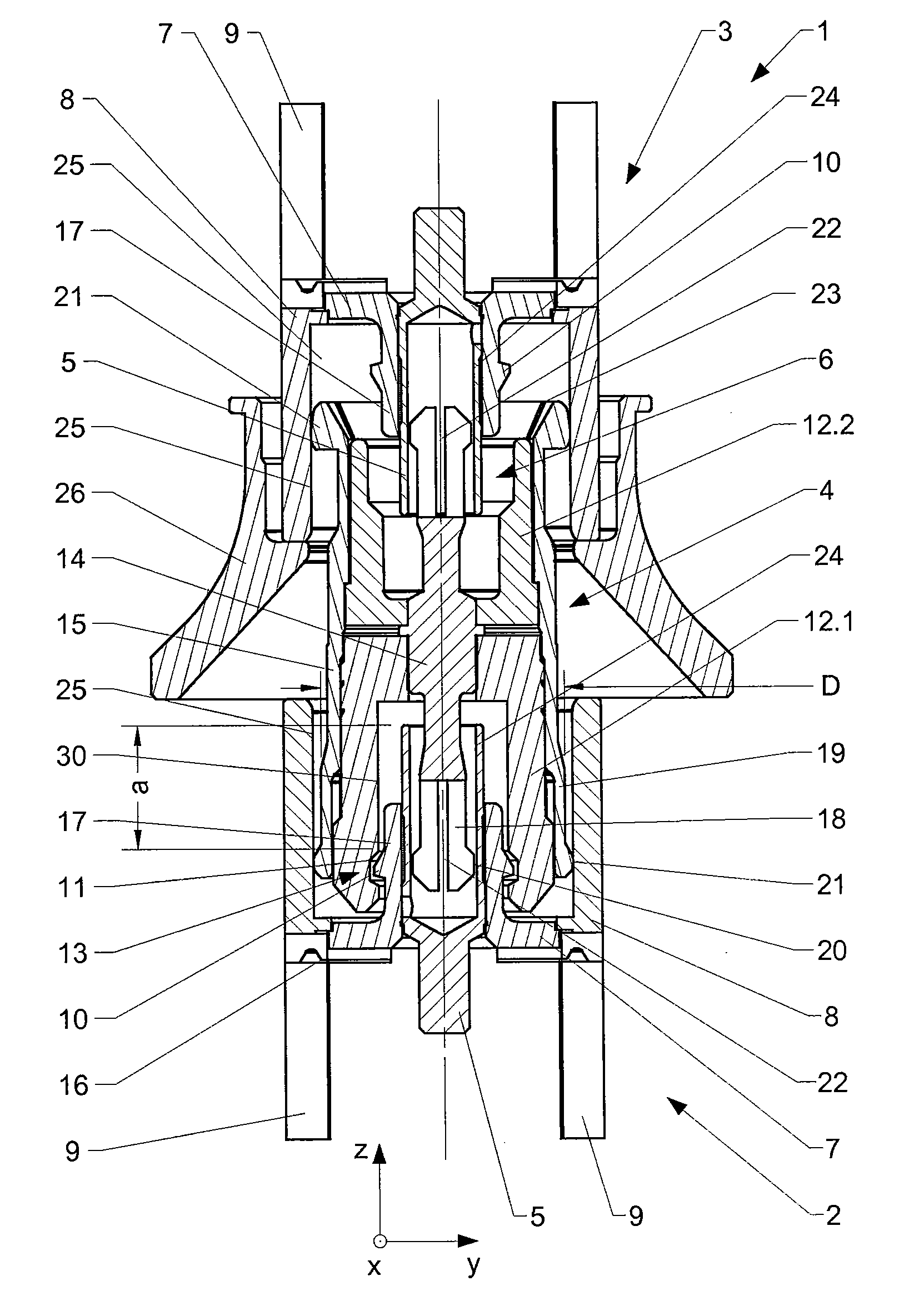
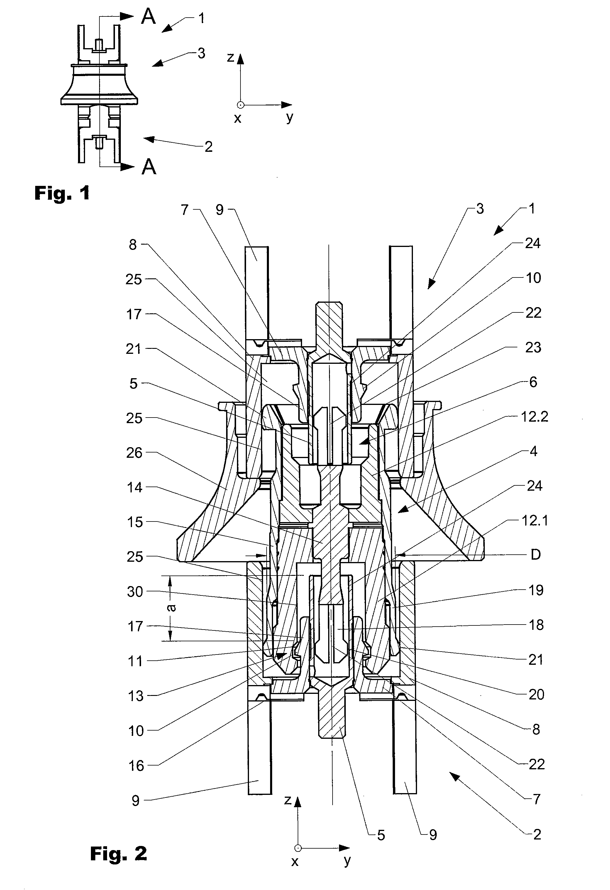
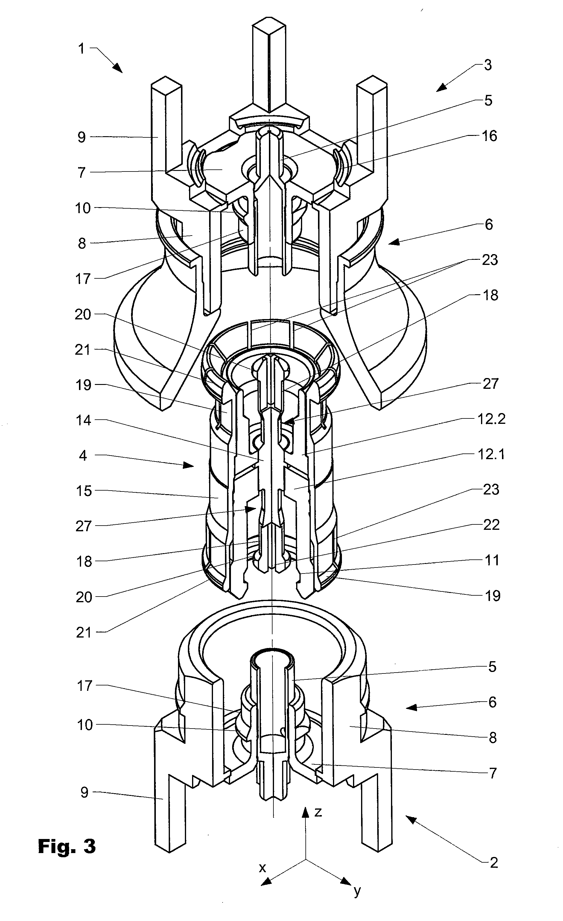
[0030]FIG. 1 shows a coaxial connector 1 according to the invention comprising a first connector part 2, a second connector part 3 and an adapter 4, which serves for operatively connecting the first to the second connector part 2, 3. The connector parts 2, 3 and also the adapter 4 have a coaxial construction.

[0031]FIG. 1 shows the coaxial connector 1 in the operatively connected state in a front view. FIG. 2 shows a sectional illustration through the connector 1 along the sectional line AA in accordance with FIG. 1. FIG. 3 shows the connector parts 2, 3 and the adaptor 4 in a perspective view obliquely from above. The connector parts 2, 3, 4 are arranged one above another, but not operatively connected. In order to afford a better understanding, the connector parts 2, 3, 4 are illustrated sectionally, such that the internals can be discerned.

[0032]In the embodiment shown, the first and second connector parts 2, 3 have an identical construction. There is the possibility, as necessary...


PUM


Abstract

The invention relates to a coaxial connector (1), comprising a first and a second connector part (2, 3) and an adapter (4) arranged therebetween. The first and the second connector part (2, 3) include a first inner conductor (5) and a first outer conductor (8), including a first internal cylindrical contact surface (24) and a second internal cylindrical contact surface (25), respectively. In a socket area (17) of the first inner conductor (5), a first mechanical operative-connection means interacts with a second mechanical operative-connection means (11) in the installed state in order to establish a mechanical connection (13) that is effective in the axial direction (z). The first inner conductor (5) protrudes beyond the level of the mechanical operative-connection means (10, 11) so the internal cylindrical contact surface (24) is able to compensate a large axial offset (dz) of the connector parts (2, 3) relative to the adapter (4).

Description

BACKGROUND OF THE INVENTION[0001]1. Field of the Invention[0002]The present invention is in the field of coaxial connectors for circuit boards.[0003]After the mounting of SMD devices on circuit boards and subsequent soldering, circuit boards are contact-connected to one another from a radiofrequency standpoint. In this case, it is necessary to compensate for location and positional inaccuracies of the SMDs (Surface Mounted Devices) in a radial and axial direction, in order that the radiofrequency properties are maintained. In general, it is necessary to connect a plurality of connectors simultaneously.[0004]2. Discussion of Related Art[0005]Various circuit board coaxial connectors are known from the prior art. Said connectors have a multipartite construction comprising a first and a second connector part, which are operatively connected to each other by means of an adapter piece. There are problems in respect of the fact that said connectors usually have a complicated construction a...

Claims


Application Information

Patent Timeline
Patent Type & Authority Applications(United States)
IPC IPC(8): H01R9/05
CPCH01R24/54H01R24/50H01R12/73H01R12/91H01R13/646
Inventor MROWKA, ECKHARD
Owner HUBERSUHNER AG
Learn More