
Optically anisotropic element, polarizing plate, stereoscopic display device, and stereoscopic display system

Inactive Publication Date: 2012-11-22
FUJIFILM CORP
View PDF2 Cites 4 Cited by
  • Summary
  • Abstract
  • Description
  • Claims
  • Application Information

AI Technical Summary

Benefits of technology

[0008]The present invention was aimed at solving the above-described problems, and an object of which is to reduce the crosstalk of stereoscopic display device equipped with an optically anisotropic element having a finely patterned optically anisotropic layer.
[0019]According to the present invention, crosstalk of a stereoscopic display device, equipped with an optically anisotropic element having a finely patterned optically anisotropic layer, may be reduced.
[0020]More specifically, the present invention successfully provides a stereoscopic display device reduced in crosstalk; and a polarizing plate, stereoscopic display system, and an optically anisotropic element used therefor.

Problems solved by technology

Commercially available film, however, has a certain extent of retardation in general, and is causative of crosstalk which has not been emerging so long as the optically-isotropic glass support has been used as the support.

Method used


Image

  • Optically anisotropic element, polarizing plate, stereoscopic display device, and stereoscopic display system
  • Optically anisotropic element, polarizing plate, stereoscopic display device, and stereoscopic display system
  • Optically anisotropic element, polarizing plate, stereoscopic display device, and stereoscopic display system

Examples


examples

[0146]The present invention will further be detailed below, referring to Examples. Note that materials, amount of use, ratio, details of treatment, procedures of treatment and so forth may be modified without departing from the spirit of the present invention. It is, therefore, to be understood that the scope of the present invention is not restrictively interpreted by Examples described below.

example a

[0147]The first and second films, having optical characteristics listed in Table below were prepared. Various types of the patterned optically anisotropic layers were respectively formed on the first film, while controlling, and then fixing, the state of alignment of a liquid crystal composition, typically making use a patterned photo-alignment film obtained by exposure of light through a mask, a patterned rubbed alignment film obtained by rubbing through a mask, or a patterned alignment film obtained by controlling expression and disappearance of interaction between an additive or the like with the alignment film, to thereby manufacture the FPRs. The liquid crystal composition adopted herein contained a polymerizable rod-like liquid crystal or a polymerizable discotic liquid crystal, optionally added with an additive for controlling alignment, and also with a polymerization initiator for promoting the polymerization. The patterned optically anisotropic layer was a patterned λ / 4 lay...

example b

[0154]Next, configurations having a patterned optically anisotropic layer disposed between the third film and the fourth film were evaluated.

[0155]The third films listed in Table 3 were respectively prepared, and the patterned optically anisotropic layers were respectively formed on the third films, while controlling, and then fixing, the state of alignment of a liquid crystal composition, typically making use a patterned photo-alignment film obtained by exposure of light through a mask, a patterned rubbed alignment film obtained by rubbing through a mask, or a patterned alignment film obtained by controlling expression and disappearance of interaction between an additive or the like with the alignment film, to thereby manufacture the FPRs. The liquid crystal composition adopted herein contained a polymerizable rod-like liquid crystal or a polymerizable discotic liquid crystal, optionally added with an additive for controlling alignment, and also with a polymerization initiator for ...


PUM


Abstract

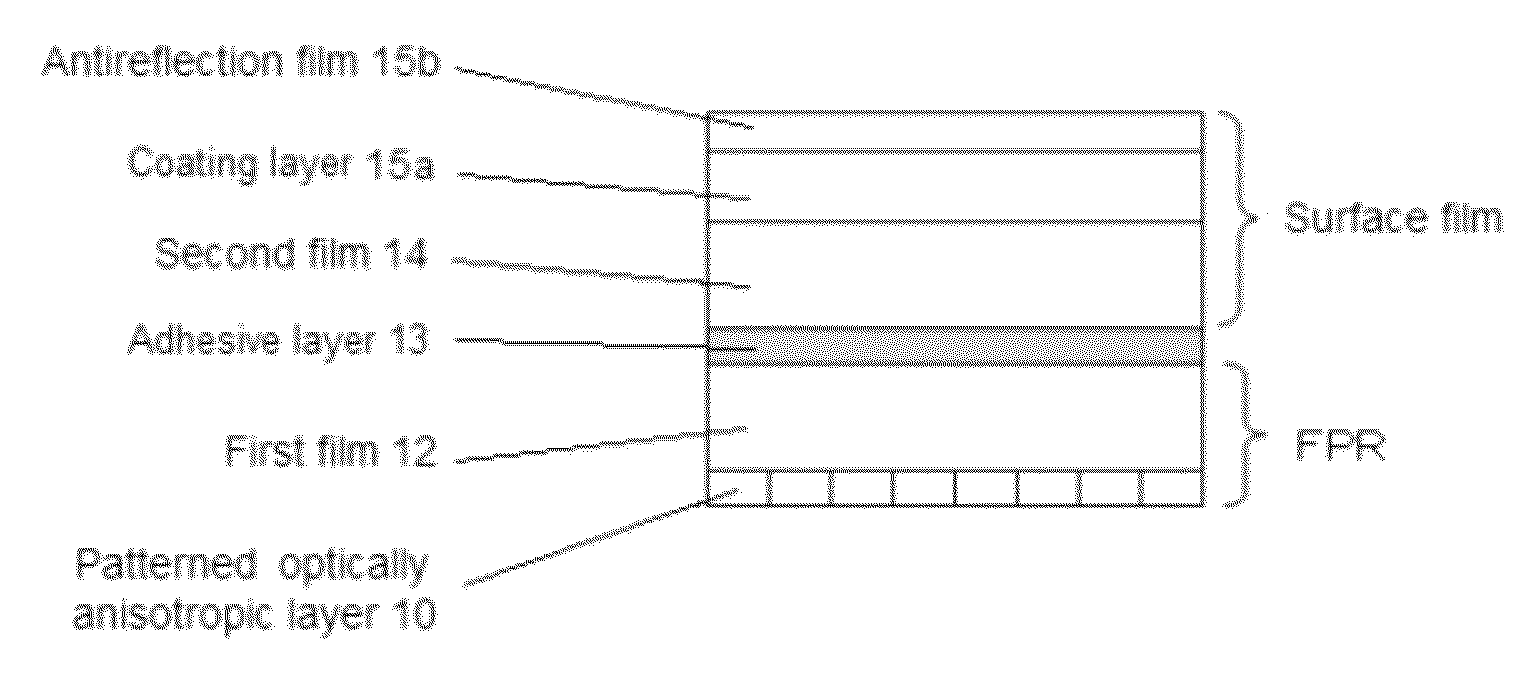
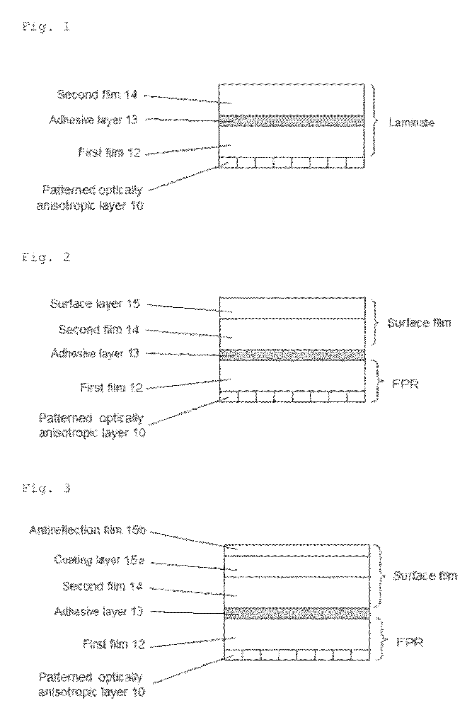
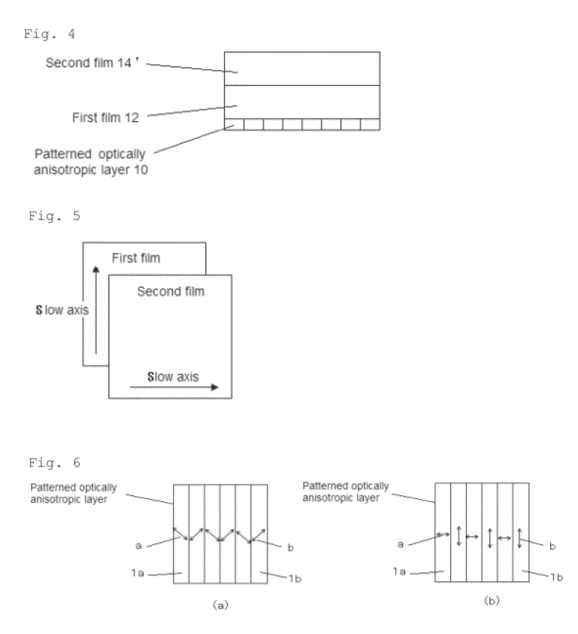
Reduction of crosstalk of a stereoscopic display device equipped with an optically anisotropic element having a finely patterned optically anisotropic layer. The optically anisotropic element has a patterned optically anisotropic layer which contains a first retardation area and a second retardation area differing from each other in at least either the direction of in-plane slow axes or the in-plane retardation, and the first and second retardation area being alternately arranged in plane, the patterned optically anisotropic layer being disposed on a surface of a laminate having a first film and a second film, while an in-plane slow axes of the first and an in-plane slow axis the second film being orthogonal to each other.

Description

[0001]The present application claims the benefit of priority from Japanese Patent Application No. 108585 / 2011, filed on May 13, 2011, Japanese Patent Application No. 093183 / 2012, filed on Apr. 16, 2012, and the contents of which are herein incorporated by reference in their entirety.BACKGROUND OF THE INVENTION[0002]1. Field of the Invention[0003]The present invention relates to an optically anisotropic element having a high-definition alignment pattern; and a polarizing plate, a stereoscopic display device, and a stereoscopic display system using the same.[0004]2. Description of the Related Art[0005]Stereo (3D) image display device for displaying stereoscopic needs an optical component typically for producing right-eye image and left-eye image which are circular polarized with reverse directionality. This sort of optical component typically adopts a patterned optically anisotropic element having areas, differing from each other in the direction of slow axis and / or retardation, perio...

Claims


Application Information

Patent Timeline
IPC IPC(8): G02F1/13363G02B27/26G02B5/30G02B30/25
CPCG02B5/3083G02F2001/133631G02F1/13363G02F1/133631
Inventor SANETO, RYUJIMORISHIMA, SHINICHIMORITA, MASATOYAMADA, NAOYOSHI
Owner FUJIFILM CORP
Learn More