Engine ignition control device

a control device and engine technology, applied in the direction of electric control, ignition automatic control, muscle operated starters, etc., can solve the problem of not being easily pushed back, achieve high start-up torque, increase engine startability, and not compromise startability

Active Publication Date: 2012-11-22
MAHLE INT GMBH
View PDF8 Cites 6 Cited by
  • Summary
  • Abstract
  • Description
  • Claims
  • Application Information

AI Technical Summary

Benefits of technology

[0016]In this case, the switching means can be configured so as to switch the determination speed in accordance with the detected start-up rotation angle such that when the start-up rotation angle detected by the start-up rotation angle detection means at the regular ignition position is less than a set angle, there is created a kickback-preventive effect within a range at which engine startability is not compromised, and when the start-up rotation angle detected by the start-up rotation angle detection means at the regular ignition position is equal to or greater than the set angle, there is created a kickback-preventive effect that is greater than the kickback-preventive effect for when the start-up rotation angle is less than the set angle.
[0017]The switching means can also be configured so as to switch the start-up regular ignition position and the maximum delay angle position in accordance with the detected start-up rotation angle such that when the start-up rotation angle detected by the start-up rotation angle detection means at the regular ignition position is less than a set angle, there is created a kickback-preventive effect within a range at which engine startability is not compromised, and when the start-up rotation angle detected by the start-up rotation angle detection means at the regular ignition position is equal to or greater than the set angle, there is created a kickback-preventive effect that is greater than the kickback-preventive effect for when the start-up rotation angle is less than the set angle.
[0018]According to the present invention, start-up rotation angle detection means is provided for detecting as a start-up rotation angle a rotation angle of a crankshaft of the engine after initiation of a start-up operation of the engine, and the control specifics of the start-up ignition controller are switched in accordance with the detected start-up rotation angle so that when the start-up rotation angle detected by the start-up rotation angle detection means is less than a set angle, increasing engine startability is prioritized and there is created a kickback-preventive effect within a range at which engine startability is not compromised, and when the detected start-up rotation angle is equal to or greater than the set angle, there is created a kickback-preventive effect that is greater than the kickback-preventive effect for when the start-up rotation angle is less than the set angle. Therefore, engine ignition is controlled so as to not compromise startability when operation force acts on the crankshaft, high start-up torque can be generated, and satisfactory engine startability can be achieved.
[0019]According to the present invention, when a state arises in which operation force ceases to be applied on the crankshaft after engine start-up is initiated and kickback readily occurs, engine ignition is controlled so as to increase the kickback-preventive effect, and the occurrence of ignition combustion kickback can therefore be reliably prevented.

Problems solved by technology

It is thought that kickback does not readily occur in the initial compression stroke because operation force acts on the crankshaft from the start-up device and the piston is therefore not readily pushed back.

Method used


Image

  • Engine ignition control device
  • Engine ignition control device
  • Engine ignition control device

Examples


first embodiment

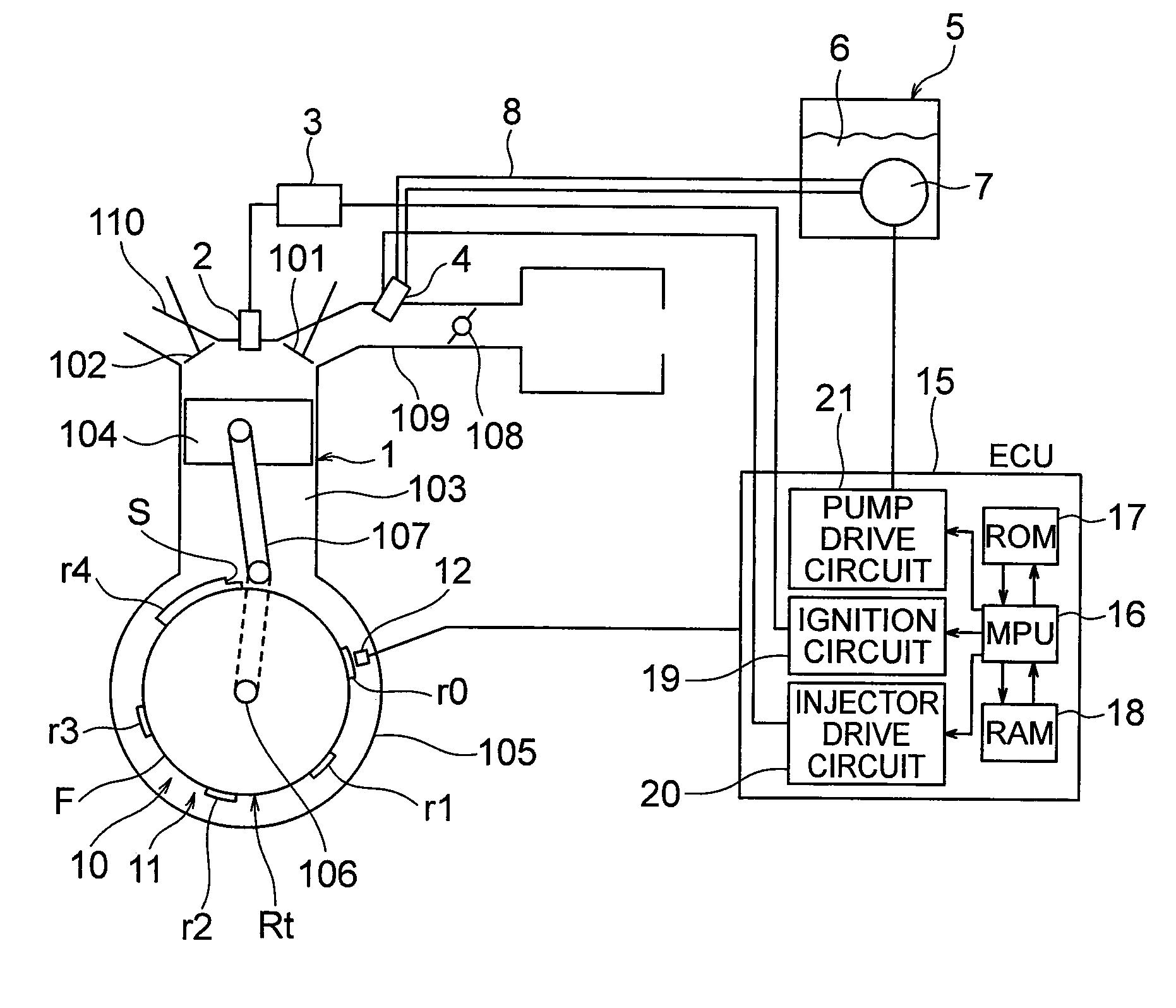
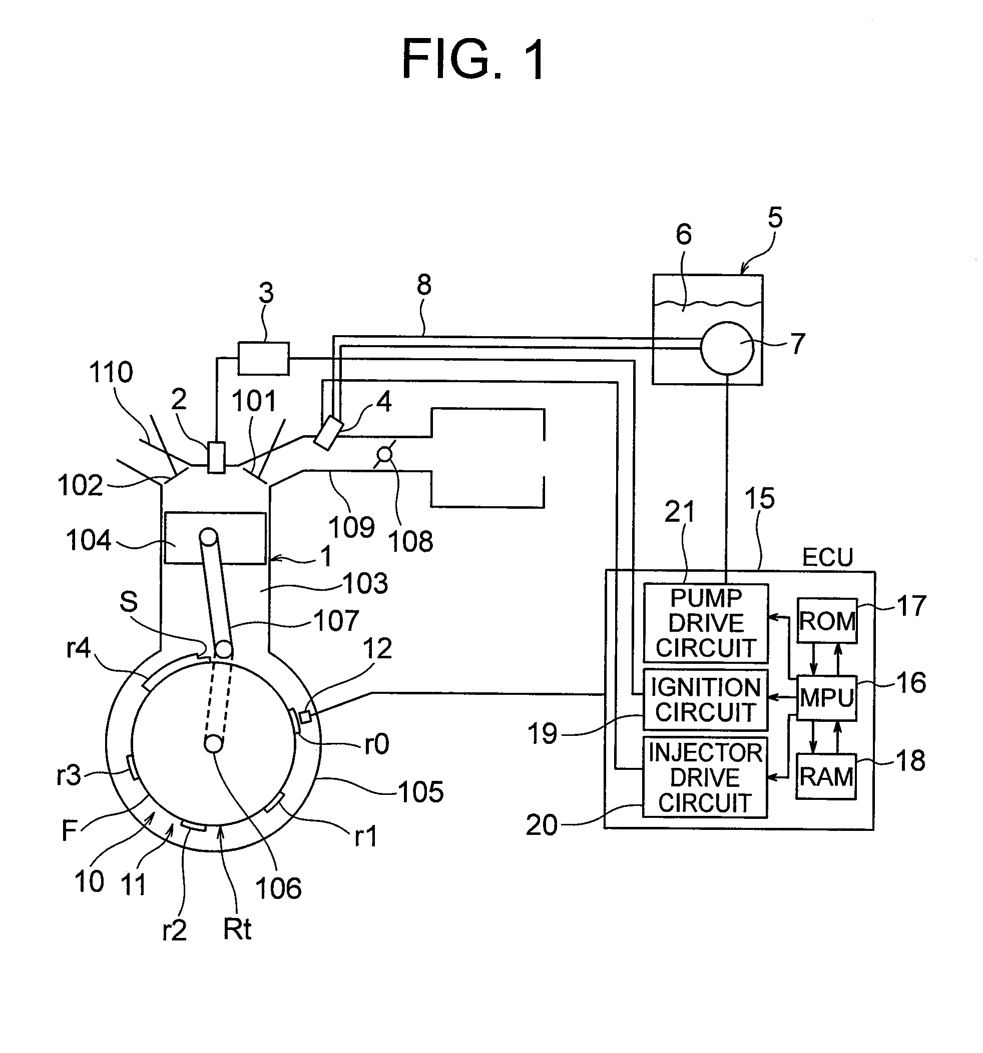
[0034]FIG. 1 schematically shows the configuration of hardware used in the embodiments of the present invention, and the numeral 1 in this drawing indicates a single-cylinder four-stroke engine. The engine 1 has a cylinder 103 having in a head an intake port and an exhaust port opened and closed by an intake valve 101 and an exhaust valve 102, a piston 104 disposed inside the cylinder 103, a crank case 105 provided in the bottom part of the cylinder 103, a crankshaft 106 disposed inside the crank case 105 and rotatably supported by the crank case 105, and a connecting rod 107 for linking the crankshaft 106 and the piston 104. A spark plug 2 is attached to the head of the cylinder 103, and a high voltage for ignition induced in a secondary coil of an ignition coil 3 is applied to the spark plug 2. An intake tube 109 having a throttle valve 108 attached inside is connected to the intake port of the engine, and an exhaust tube 110 is connected to the exhaust port. An injector (a fuel i...

second embodiment

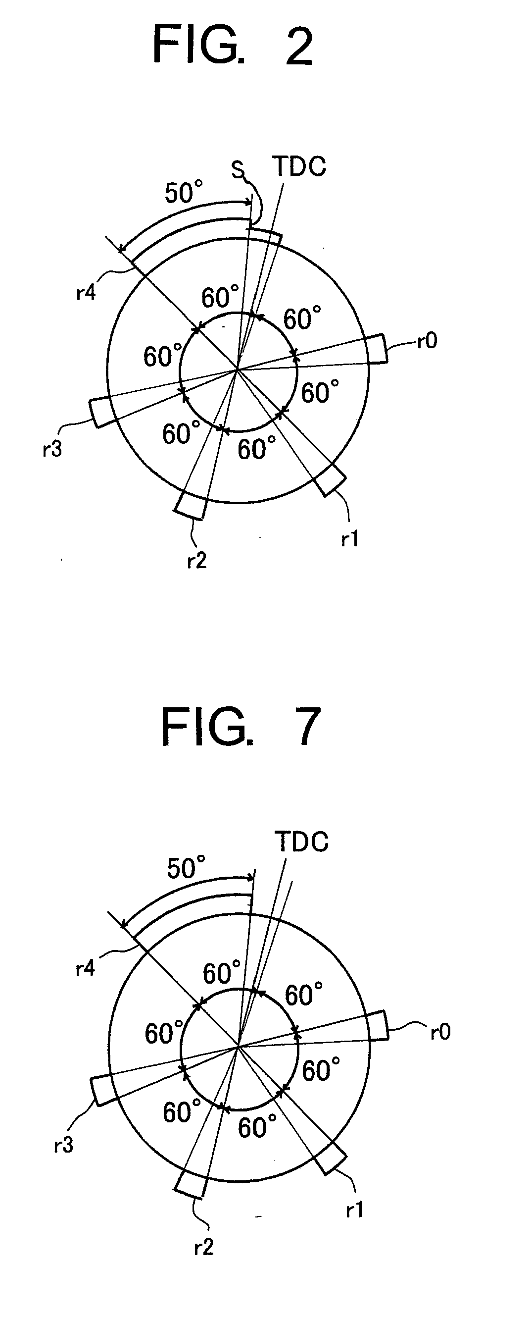
[0075]In the first embodiment, a protuberance having a level difference at some point was used as the reluctor r4 for generating a reference pulse, but in the present embodiment, a reluctor r4 composed of an arcuate protuberance having no level difference at any point is used as shown in FIG. 7. In this case, the arc angle between the poles of the reluctor r4 is made equal to the angle (50° in the present embodiment) from the first reference crank angle position θ4A to the second reference crank angle position θ4B. FIG. 8 shows the waveform of the crank angle signal outputted by the crank angle sensor 12 when such a reluctor is provided. The crank angle signal shown in FIG. 8 has a waveform that omits the pulse P4C from the waveform shown in FIG. 3.

[0076]In cases in which a crank angle signal such as the one shown in FIG. 8 is used, a first start-of-delaying-angle determination value Ts1 used when kick force is applied to the crankshaft and a second start-of-delaying-angle determina...

third embodiment

[0079]In the above embodiments, the start-of-delaying-angle determination value and end-of-delaying-angle determination value were switched according to the start-up rotation angle detected by the start-up rotation angle detection means 36, but in the third embodiment of the present invention, the regular ignition position and maximum delay angle position at start-up are switched according to the start-up rotation angle detected in the regular ignition position. A block diagram showing the configuration of the ignition control device according to the present embodiment is shown in FIG. 10. The block diagram of FIG. 10 is identical to the block diagram of FIG. 4 except for the switching means 37 being configured so as to switch the regular ignition position and the maximum delay angle position. The reluctor detected by the crank sensor 12 in the present embodiment is the same as the one shown in FIG. 2, and the waveform of the crank angle signal outputted by the crank angle sensor 12...


PUM


Abstract

An engine ignition control device comprising: a start-up ignition controller having a function for preventing the occurrence of kickback by either delaying an ignition position of an engine or stopping ignition; start-up rotation angle detection means for detecting a rotation angle of a crankshaft of the engine after initiation of a start-up operation of the engine; and switching means for switching control specifics of the start-up ignition controller in accordance with the detected start-up rotation angle so that when the detected start-up rotation angle is less than a set angle, there is created a kickback-preventive effect within a range at which engine startability is not compromised, and when the detected start-up rotation angle is equal to or greater than the set angle, there is created a kickback-preventive effect that is greater than the kickback-preventive effect for when the start-up rotation angle is equal to or less than the set angle.

Description

TECHNICAL FIELD OF THE INVENTION[0001]The present invention relates to an engine ignition control device for controlling ignition of an engine started up using human power.PRIOR ART[0002]In an engine in which start-up is performed by a start-up device operated by human power, such as a recoil starter or a kick starter, when rotational force applied to a crankshaft at start-up is insufficient, a phenomenon occurs in which the rotational force is surpassed by reaction force that occurs with the compression of gas inside the cylinder and a piston is pushed back just short of top dead center. When ignition of the engine is performed before the piston reaches top dead center in a state in which insufficient rotational force is applied to the crankshaft by the start-up operation, a phenomenon occurs in which the piston is pushed back by explosive force. The kickback occurring due to the rotational force being surpassed by the compression force is referred to as compression kickback, and t...

Claims


Application Information

Patent Timeline
Patent Type & Authority Applications(United States)
IPC IPC(8): F02P5/15F02N3/00
CPCF02D41/009F02N3/04Y02T10/46F02P5/1506F02D2041/0092F02D2250/06F02N2250/04F02P5/1553F02P5/1558F02P7/067F02P7/07F02P9/005F02P11/00Y02T10/40
Inventor SATO, HIROYASUUEMURA, KIYOSHISEKITA, TOMOAKI
Owner MAHLE INT GMBH
Why Eureka
Try Eureka