
Needle Bearing Hinge Assembly

a technology of needle bearings and hinge assemblies, which is applied in the direction of hinges, wing accessories, manufacturing tools, etc., can solve the problems of not disclosing the enclosed needle bearing assembly that offers improved freedom of rotation, and the device of lubricating grease or oil is not available after the device is deployed, so as to improve the operation, reduce the load of the hinge, and improve the effect of operation

Inactive Publication Date: 2012-11-22
GIBSON THOMAS
View PDF17 Cites 5 Cited by
  • Summary
  • Abstract
  • Description
  • Claims
  • Application Information

AI Technical Summary

Benefits of technology

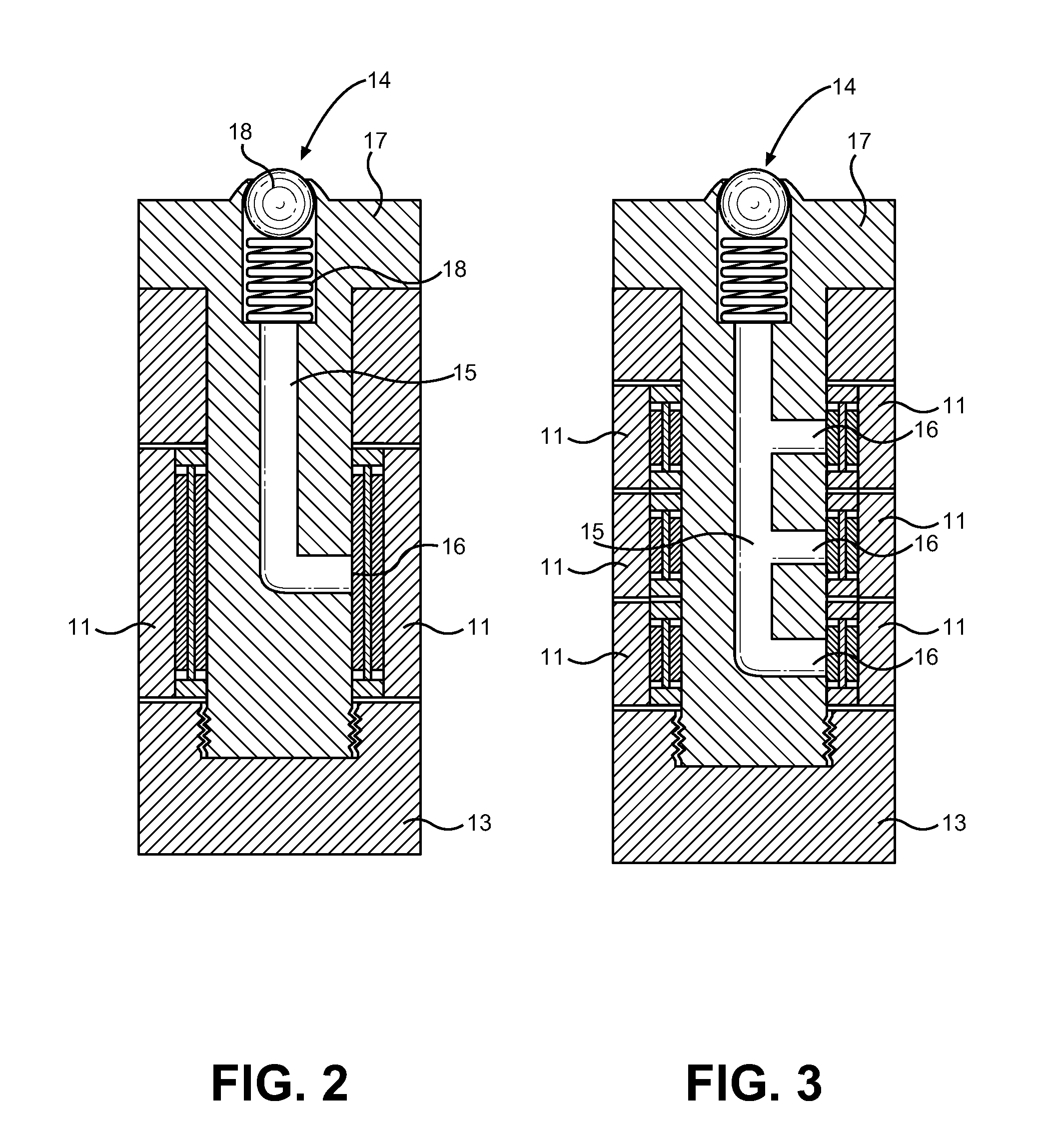
[0010]In view of the foregoing disadvantages inherent in the known types of hinge bearing devices now present in the prior art, the present invention provides a new hinge assembly wherein the same can be utilized for providing convenience for the user when supporting higher hinge loads, reducing wear over long-term hinge installations and improving operation thereof.
[0012]It is another object of the present invention to provide a needle bearing hinge assembly that offers improved operation, useful life and load capacity of the hinge over existing hinge pin assemblies.
[0013]Another object of the present invention is to provide a needle bearing hinge assembly having internal needle bearings, a pathway for inserting grease through the assembly and to the bearings, and a grease fitting for easy access to the pathway after installation of the hinge assembly.
[0014]Yet another object of the present invention is to provide a needle bearing hinge device that is provided in an enclosed and removable assembly, wherein the assembly is insertable into the hinge in place of a simple pin bearing surface to improve free rotation and operation of the hinge.

Problems solved by technology

While providing an assembly that offers needle bearings in a door hinge application, the Jesse device offers no means of inserting lubricating grease or oil into the bearing assembly after the device is deployed.
However, these devices do not disclose an enclosed needle bearing assembly that offers improved freedom of rotation, improved lubrication and increased load capacity over simple hinge pins.

Method used


Image

  • Needle Bearing Hinge Assembly
  • Needle Bearing Hinge Assembly
  • Needle Bearing Hinge Assembly

Examples


Embodiment Construction

[0020]Reference is made herein to the attached drawings. Like reference numerals are used throughout the drawings to depict like or similar elements of the hinge bearing device. For the purposes of presenting a brief and clear description of the present invention, the preferred embodiment will be discussed as used for replacement of a hinge pivot pin with one that incorporates needle bearings and a means of lubricating the assembly during operation. The figures are intended for representative purposes only and should not be considered to be limiting in any respect.

[0021]Referring now to FIG. 1, there is shown a frontal perspective view of a needle bearing assembly as described by the present invention, wherein a cut-away window shows its internal structure. The assembly comprises at least one needle bearing 12, an outer rotating surface 11 and an internal lubrication conduit 15. As shown in FIG. 1, the assembly comprises three needle bearings 12 and three independently rotating surf...


PUM


Abstract

Disclosed is an enclosed needle bearing hinge mechanism having externally rotatable race surfaces, internal needle bearings, an internal pathway for introducing grease into the assembly for improved lubrication, reduced wear and a construction adapted to support large door or latch loads. The assembly comprises a housing having at least one needle bearing in contact with an outer rotating race, stationary or counter-rotating interior races, a central pin shaft and an internal pathway for lubrication to be communicated from a topmost grease fitting to the contact interface between the needle bearing and outer rotating race. One or plurality of needle bearing assemblies and counter-rotating outer races may be present within the assembly, each with an independent grease pathway branch. The pathway comprises a hollow internal conduit that allows lubricant to contact each needle bearing in the assembly, reducing friction and improving longevity of the hinge bearing assembly.

Description

CROSS REFERENCE TO RELATED APPLICATION[0001]This application claims the benefit of U.S. Provisional Application No. 61 / 487,983 filed on May 19, 2011, entitled “Needle Bearing Hinges.” The patent application identified above is incorporated here by reference in its entirety to provide continuity of disclosure.BACKGROUND OF THE INVENTION[0002]1. Field of the Invention[0003]The present invention relates to rotating door and hinge mechanisms. More specifically, the present invention relates to a hinge bearing assembly having improved construction that facilitates improved lubrication, reduced wear and improved operating of a hinge joint. The construction of the device includes at least one needle bearing assembly, wherein the needle bearings offer improved free rotation of the hinge joint over metal-to-metal non-rotating surfaces and simple pin hinge mechanisms. The assembly further incorporates an ability to easily grease the bearings while installed, further reducing friction, squeaki...

Claims


Application Information

Patent Timeline
IPC IPC(8): E05D11/02E05D11/04
CPCE05D11/02E05D11/04E05Y2900/132F16C33/6622Y10T16/5377Y10T16/5379Y10T16/557Y10T16/5373F16C19/48
Inventor GIBSON, THOMAS
Owner GIBSON THOMAS
Learn More