
Protective helmet

Active Publication Date: 2012-11-22
MSA PRODION FRANCE
View PDF10 Cites 7 Cited by
  • Summary
  • Abstract
  • Description
  • Claims
  • Application Information

AI Technical Summary

Benefits of technology

[0010]Generally, the present invention provides a protective helmet that addresses some or all of the aforementioned drawbacks and deficiencies. Preferably, the present invention provides a protective helmet that allows for the attachment of an electronic connecting device that does not substantially diminish the wearer's protection and / or comfort. Preferably, the present invention provides a protective helmet that allows for the attachment of an electronic connecting device that reduces the risk of contacting the electronic connecting device with other outside objects. Preferably, the present invention provides a protective helmet that allows for the attachment of an electronic connecting device that reduces the risk of catching or damaging cables or other components of the electronic connecting device.
[0012]Thus, the helmet according to the present invention provides a connecting device that is at least partly integrated into the thickness of the shell. This thereby limits the bulk of portions of this device that protrude towards the inside and outside of the shell. Further, the helmet according to the present invention reduces or eliminates discomfort to the wearer, and considerably reduces the risks of catching parts of the helmet in various outside elements. Moreover, if a cavity is provided in the cap to house part of the connecting device, it will have small dimensions relative to existing designs. The protection granted by the helmet is therefore not degraded by the presence of the connecting device.
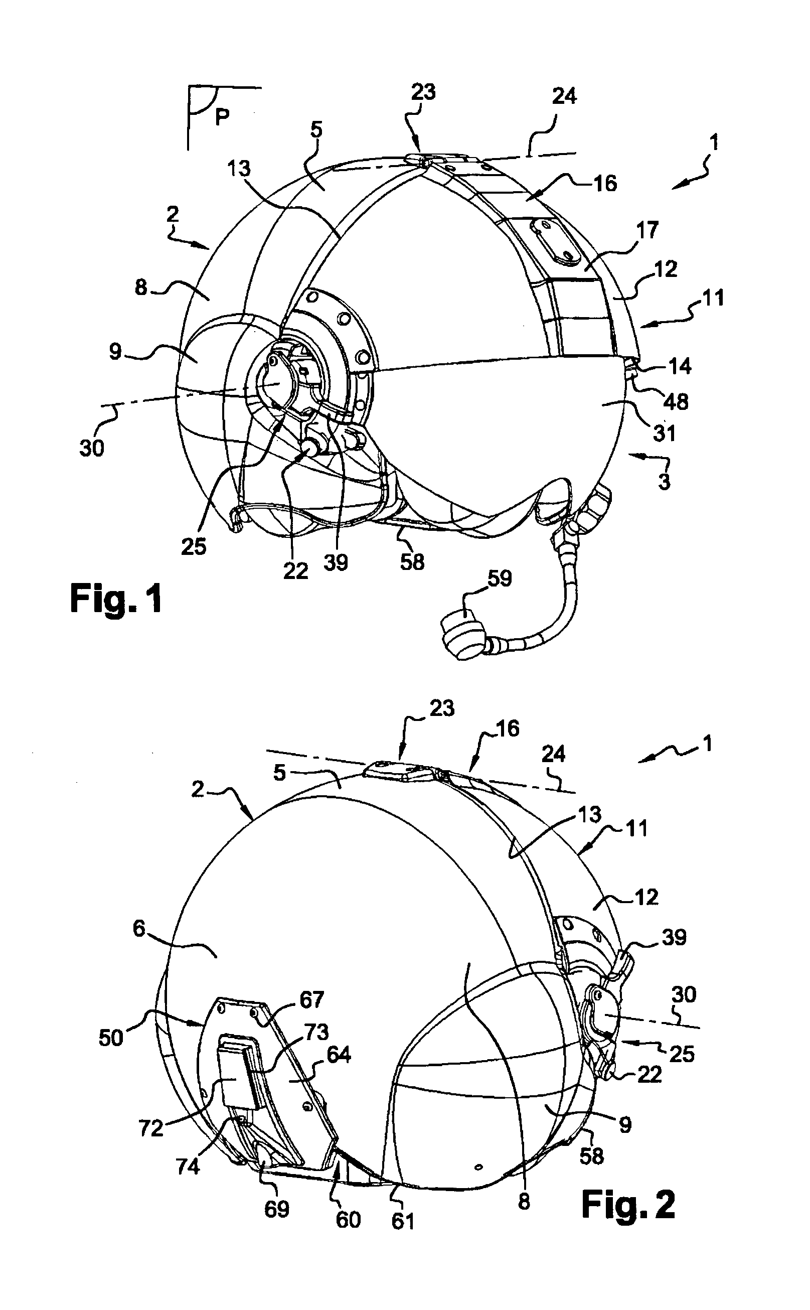
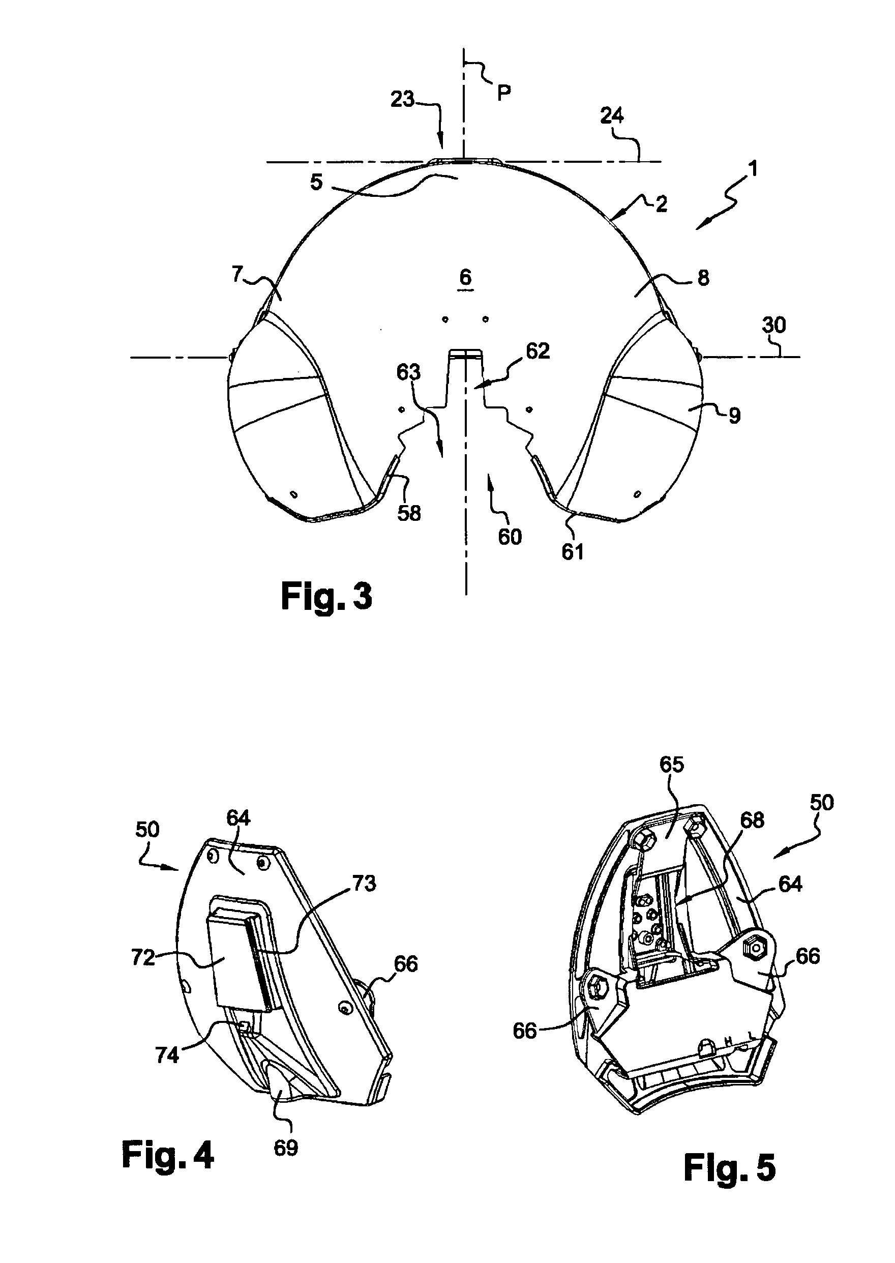
[0013]The opening is, for example, formed in the back portion of the helmet. This prevents unbalancing the helmet. Further, in one preferred and non-limiting embodiment, the opening is formed in the back portion of the helmet and emerges on the lower edge of said back portion. The presence of such an opening grants the helmet a certain elasticity that makes it possible to have a very enveloping shell without harming the ease of placement of the helmet on the head. Moreover, with this structure, it is possible to insert the connecting device through the lower part of the helmet by moving it upwards to cause it to penetrate the opening. Therefore, the positioning function is quick and simple.
[0017]In a further preferred and non-limiting embodiment, the electronic connecting device includes a housing having a main wall and at least one fastening lug that is connected to the main wall such that, in the mounted position, the shell is sandwiched between the main wall and the fastening lug. According to another preferred and non-limiting embodiment, the main wall of the electronic connecting device is situated on the outer side of the shell, and this main wall is substantially sphere portion-shaped extending the shape of the shell at the opening in which the electronic connecting device is mounted. This further improves the integration of the electronic connecting device in the shell and the limitation of the protruding parts.
[0020]Due to the presence of the articulating or hinge means, which do not require the support element to be completely removed in relation to the shell, accidental pulling or removal of the cables is avoided when the support element is raised to change the visor(s) of the shell. In practice, the cable is fastened under the shell and under the support element, and is protected by a piece, called a cap, fastened under the shell. For example, the cable substantially borders the longitudinal plane of symmetry of the helmet.

Problems solved by technology

This thereby limits the bulk of portions of this device that protrude towards the inside and outside of the shell.

Method used


Image

  • Protective helmet
  • Protective helmet
  • Protective helmet

Examples


Embodiment Construction

[0029]For purposes of the description hereinafter, the terms “end”, “upper”, “lower”, “right”, “left”, “vertical”, “horizontal”, “top”, “bottom”, “lateral”, “longitudinal” and derivatives thereof shall relate to the invention as it is oriented in the drawing figures. However, it is to be understood that the invention may assume various alternative variations and step sequences, except where expressly specified to the contrary. It is also to be understood that the specific devices and processes illustrated in the attached drawings, and described in the following specification, are simply exemplary embodiments of the invention. Hence, specific dimensions and other physical characteristics related to the embodiments disclosed herein are not to be considered as limiting.

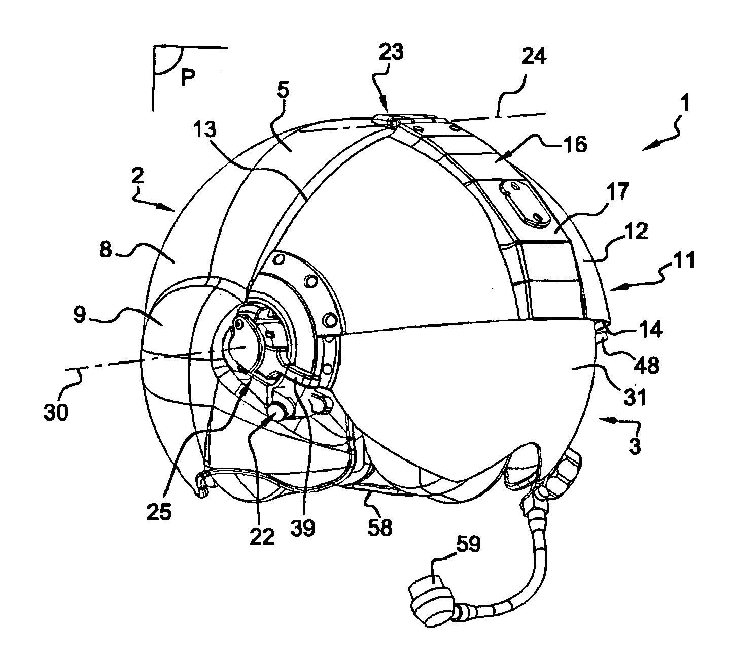
[0030]With reference to FIGS. 1-3 and 6-8, provided is a helmet 1, which includes a rigid shell 2 that is intended to fit a wearer's head, and is, for example, made from a composite material. The shell 2 has a longitudin...


PUM


Abstract

A protective helmet including a rigid shell and an electronic connecting device mounted on the shell, the connecting device including an electronic circuit, first means for connecting said circuit to a power supply system, and second means for connecting said circuit to at least one accessory that can be mounted on the helmet, wherein the connecting device is mounted on the shell in an opening formed in said shell.

Description

CROSS REFERENCE TO RELATED APPLICATIONS[0001]This application claims priority to French Patent Application No. FR10 / 51203, filed Feb. 19, 2010, which is incorporated herein by reference in its entirety.BACKGROUND OF THE INVENTION[0002]1. Field of the Invention[0003]The present invention relates generally to protective helmets and headwear, and in particular to helmets worn by specific personnel in certain environments, including helmets worn by airplane or helicopter flight personnel.[0004]2. Description of Related Art[0005]A helmet typically includes a rigid outer shell having a generally spherical shape, intended to cover the wearer's head, and a facial opening for the wearer's face. Fastened on the inner side of the shell are damping and / or padding elements, which include a cap, generally made of polystyrene, and cushions, normally located at the neck.[0006]Such a helmet is traditionally provided with communication members, in particular a microphone and loudspeakers, which allow...

Claims


Application Information

Patent Timeline
IPC IPC(8): A42B3/04A42B3/12
CPCA42B3/0406
Inventor BASSON, GILLES
Owner MSA PRODION FRANCE
Learn More