
Photobioreactor for culturing microalgae using hollow fiber membrane

a photobioreactor and microalgae technology, applied in bioreactors/fermenters, biomass after-treatment, biochemical apparatus and processes, etc., can solve the problems of large installation space, low productivity per unit area, temperature, ph and other factors that are necessary for etc., to facilitate the growth of microalgae, increase the saturation rate of carbon dioxide, and maximize carbon dioxide

Inactive Publication Date: 2012-11-15
HYUNDAI MOTOR CO LTD +1
View PDF8 Cites 9 Cited by
  • Summary
  • Abstract
  • Description
  • Claims
  • Application Information

AI Technical Summary

Benefits of technology

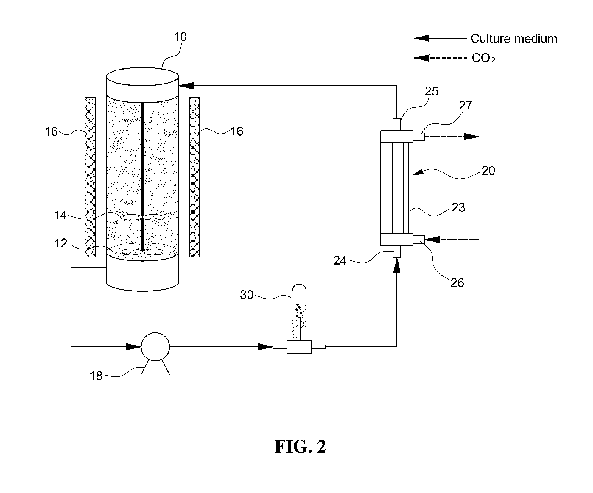
[0009]The present invention is directed to providing a high-speed photobioreactor for culturing microalgae using a hollow fiber membrane capable of facilitating the growth of microalgae and maximizing carbon dioxide by using a hollow fiber membrane having a large membrane surface area and thus increases the saturation rate of carbon dioxide in the culture medium.
[0014]Furthermore, another hollow fiber membrane module may be provided between the hollow fiber membrane module and the reactor main body, and a gas inlet of the another hollow fiber membrane module may be connected to a gas outlet of the hollow fiber membrane module to increase contact time of carbon dioxide with the culture medium.

Problems solved by technology

However, a large installation space is required because the productivity per unit area is also low and it is difficult to control the amount of nutrients, temperature, pH and other factors that are necessary for growth of microalgae.
Microalgae grows so slowly because CO2 gas is injected into the reactor simply by a bubbling method and thus does not ensure a lengthy contact time of CO2 with the microalgae due to the low solubility of CO2 in water.
Additionally, since the gas emitted from the culture medium is not completely CO2-free, an additional collecting device is required to reuse the gas from the culture medium.
Furthermore, there are also problems in reuse of the water and harvesting of the microalgae since the culture medium and the microalgae should be managed separately.

Method used


Image

  • Photobioreactor for culturing microalgae using hollow fiber membrane
  • Photobioreactor for culturing microalgae using hollow fiber membrane
  • Photobioreactor for culturing microalgae using hollow fiber membrane

Examples


Embodiment Construction

[0024]Hereinafter, reference will now be made in detail to various embodiments of the present invention, examples of which are illustrated in the accompanying drawings and described below. While the invention will be described in conjunction with exemplary embodiments, it will be understood that the present description is not intended to limit the invention to those exemplary embodiments. On the contrary, the invention is intended to cover not only the exemplary embodiments, but also various alternatives, modifications, equivalents and other embodiments, which may be included within the spirit and scope of the invention as defined by the appended claims.

[0025]Unless specifically stated or obvious from context, as used herein, the term “about” is understood as within a range of normal tolerance in the art, for example within 2 standard deviations of the mean. About can be understood as within 10%, 9%, 8%, 7%, 6%, 5%, 4%, 3%, 2%, 1%, 0.5%, 0.1%, 0.05%, or 0.01% of the stated value. Un...


PUM


Abstract

Disclosed is a high-speed photobioreactor for culturing microalgae using a hollow fiber membrane. More particularly a high-speed photobioreactor for culturing microalgae using a hollow fiber membrane capable of facilitating growth of microalgae and maximizing carbon dioxide fixation by increasing the rate of carbon dioxide saturation in a culture medium. Specifically, a high-speed photobioreactor for culturing microalgae using a hollow fiber membrane includes a reactor main body for culturing microalgae; a hollow fiber membrane module for supplying carbon dioxide into a culture medium in the reactor main body; a culture medium circulation pump for circulating the culture medium; and a defoamer for removing foams produced in the culture medium.

Description

CROSS-REFERENCE TO RELATED APPLICATIONS[0001]This application claims priority under 35 U.S.C. §119 to Korean Patent Application No. 10-2011-0044309, filed on May 12, 2011, in the Korean Intellectual Property Office, the disclosure of which is incorporated herein by reference in its entirety.BACKGROUND[0002](a) Technical Field[0003]The present invention relates to a high-speed photobioreactor for culturing microalgae using a hollow fiber membrane. More particularly, the present invention relates to a high-speed photobioreactor for culturing microalgae using a hollow fiber membrane capable of facilitating growth of microalgae and maximizing carbon dioxide fixation by increasing the rate of carbon dioxide saturation in a culture medium.[0004](b) Background Art[0005]Various attempts have been made to solve the planet wide environmental problems associated with global warming and fossil fuel depletion. Among some of these attempts is a method of biologically reducing CO2 and producing bi...

Claims


Application Information

Patent Timeline
IPC IPC(8): C12M1/04
CPCC12M21/02C12M29/16C12M29/18C12M1/06C12M1/12C12M3/02C12M3/06
Inventor JUNG, BUM SUKLIM, JOO HWANGOH, DAE YOUNGHA, SOO HYUNLEE, WON BAEBAE, SHIN TAE
Owner HYUNDAI MOTOR CO LTD
Learn More