
Wavelength-specific wide impinging angle limiter

a wide-angle, limiter technology, applied in the direction of spectacles/goggles, instruments, applications, etc., can solve the problems of filtering light in a wide spectral band around the designed wavelength, affecting the use and applicability of filters, and having permanent or temporary damage to the eye of lasers

Active Publication Date: 2012-11-15
ELBIT SYST LTD
View PDF3 Cites 16 Cited by
  • Summary
  • Abstract
  • Description
  • Claims
  • Application Information

AI Technical Summary

Benefits of technology

The present patent relates to an optical device called an impingement angle-independent wavelength-specific limiter, which can limit the amount of light that has different wavelengths. The device includes a stack of wavelength-specific limiters that are activated by different wavelengths of light. Each limiter is designed to limit the corresponding wavelength of light that has an intensity above a certain threshold. The device is not affected by the angle at which the light enters the device. The technical effect of this invention is to provide a way to limit the amount of light that has different wavelengths, which can be useful in various applications such as optical communication systems or optical sensors.

Problems solved by technology

Many lasers have powers that are permanently or temporarily damaging to the eye and / or various electronic sensors.
Moreover, these filters do not transmit light in a wide spectral band around the designed wavelength, to accommodate for the angles of impingement that are not perpendicular to the surface.
Thus, the use and applicability of these filters are limited.
Thin film interference filters designed to block three known wavelengths, e.g., blue, green and red, at angles up to 30° will allow only about 30% of the visible light to pass and thus will result in a poor image.
There is an unaddressed need in the art for an impingement angle-independent, wavelength-specific limiter for these applications.
Despite its remarkable potential utility, the practical use of up-conversion has been extremely limited.
In many applications, there is insufficient UV and short wave visible light radiation to actuate the photochromic material.
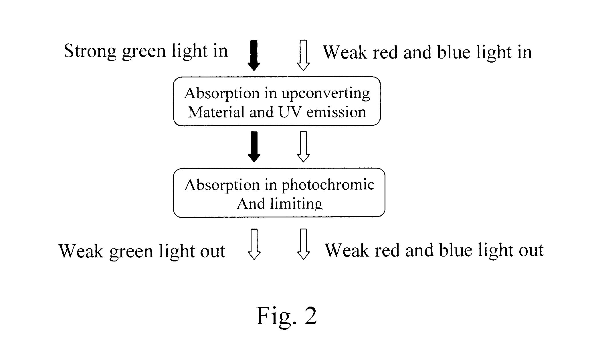
The current disclosure relates to absorption of impinging angle-independent laser light in up-converting materials, and the use of the re-emitted light to tint a photochromic dye, which in turn can limit the transmission of the exciting laser.

Method used


Image

  • Wavelength-specific wide impinging angle limiter
  • Wavelength-specific wide impinging angle limiter
  • Wavelength-specific wide impinging angle limiter

Examples


Embodiment Construction

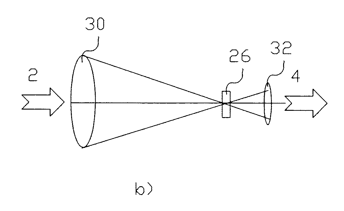
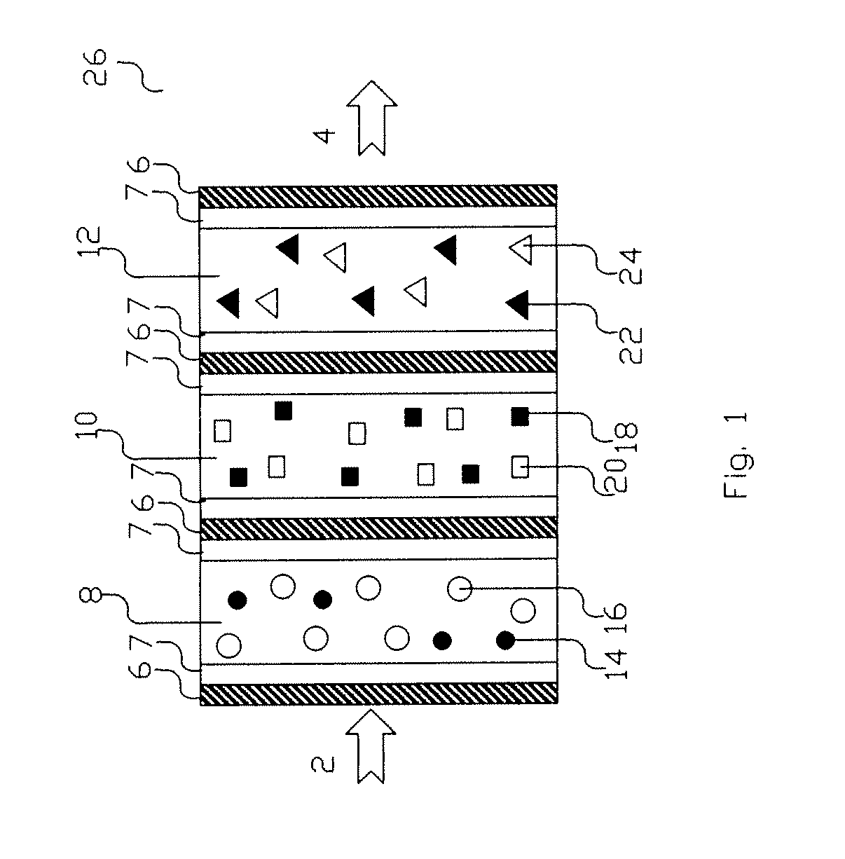
[0020]FIG. 1 illustrates an impingement angle-independent, wavelength-specific limiters stack 26 that includes layers 8, 10 and 12 of wavelength-specific limiters separated by reflecting layers 7 and absorbing layers 6 that are absorbing for the up-converted light. The impinging light 2 consists of the whole spectrum and, in addition, a strong part, e.g., a 535 nm-wavelength green laser, the second harmonic of the widely used Neodymium laser. The weak part of the spectrum passes unchanged, whereas the green strong light is absorbed in up-converting particles 14, inside composition layer 8, emitting UV light that is absorbed by photochromic material 16. Material 16, when excited by UV light, becomes green laser power absorbing, and thus reduces the 535 nm-wavelength green laser power, effectively limiting it.

[0021]A similar process takes place for blue laser at composition 10, where the blue strong light is absorbed in up-converting particles 18, emitting UV light that is absorbed by...


PUM


Abstract

An impingement angle-independent wavelength-specific limiter includes a stack of wavelength-specific limiters configured to limit impinging light having a plurality of different wavelengths. The stack includes a plurality of wavelength-specific limiters. Each one of the plurality of wavelength-specific limiters is activated by a corresponding wavelength of the impinging light and is configured to limit the corresponding wavelength of the impinging light.

Description

PRIORITY CLAIM[0001]This application claims priority to U.S. Provisional Application No. 61 / 484,844 filed May 11, 2011, the contents of which are hereby incorporated by reference herein in its entirety.FIELD OF THE INVENTION[0002]The present disclosure relates to optical power-limiting devices, and more particularly, to wavelength-specific wide impinging-angle optical power-limiting passive devices and to methods for limiting wavelength-specific wide impinging-angle optical power transmission through filters, wide impinging-angle optical power reflection mirrors, using absorption changes in a stack of photochromic materials, having the property of being activated by and blocking the same specific wavelength.[0003]The present disclosure also relates to the production of filters, mirrors and other optical articles protected against laser dazzling, where the dazzling laser is blue, green, red or any specific wavelength.BACKGROUND OF THE INVENTION[0004]Many hand-held lasers are used as ...

Claims


Application Information

Patent Timeline
Patent Type & Authority Applications(United States)
IPC IPC(8): G02B5/22
CPCG02B5/23G02C7/102G02F2202/14B23K2201/06G02F2203/52B23K2101/06
Inventor OFIR, YUVALDONVAL, ARIELAORON, MOSHENEVO, DORON
Owner ELBIT SYST LTD
Learn More