
High Resolution Electrical Stimulation Leads

a high-resolution, lead-based technology, applied in the direction of internal electrodes, artificial respiration, therapy, etc., can solve the problem of too fast depletion of batteries, and achieve the effect of easy application of field steering

Active Publication Date: 2012-11-01
MEDTRONIC BAKKEN RES CENT
View PDF1 Cites 32 Cited by
  • Summary
  • Abstract
  • Description
  • Claims
  • Application Information

AI Technical Summary

Benefits of technology

[0011]It is an object of the invention to enable easily applying field steering in systems with high resolution probes. In particular, it is an object of the invention to provide a system and a method applying current steering with high resolution probes without unduly increasing the power consumed.
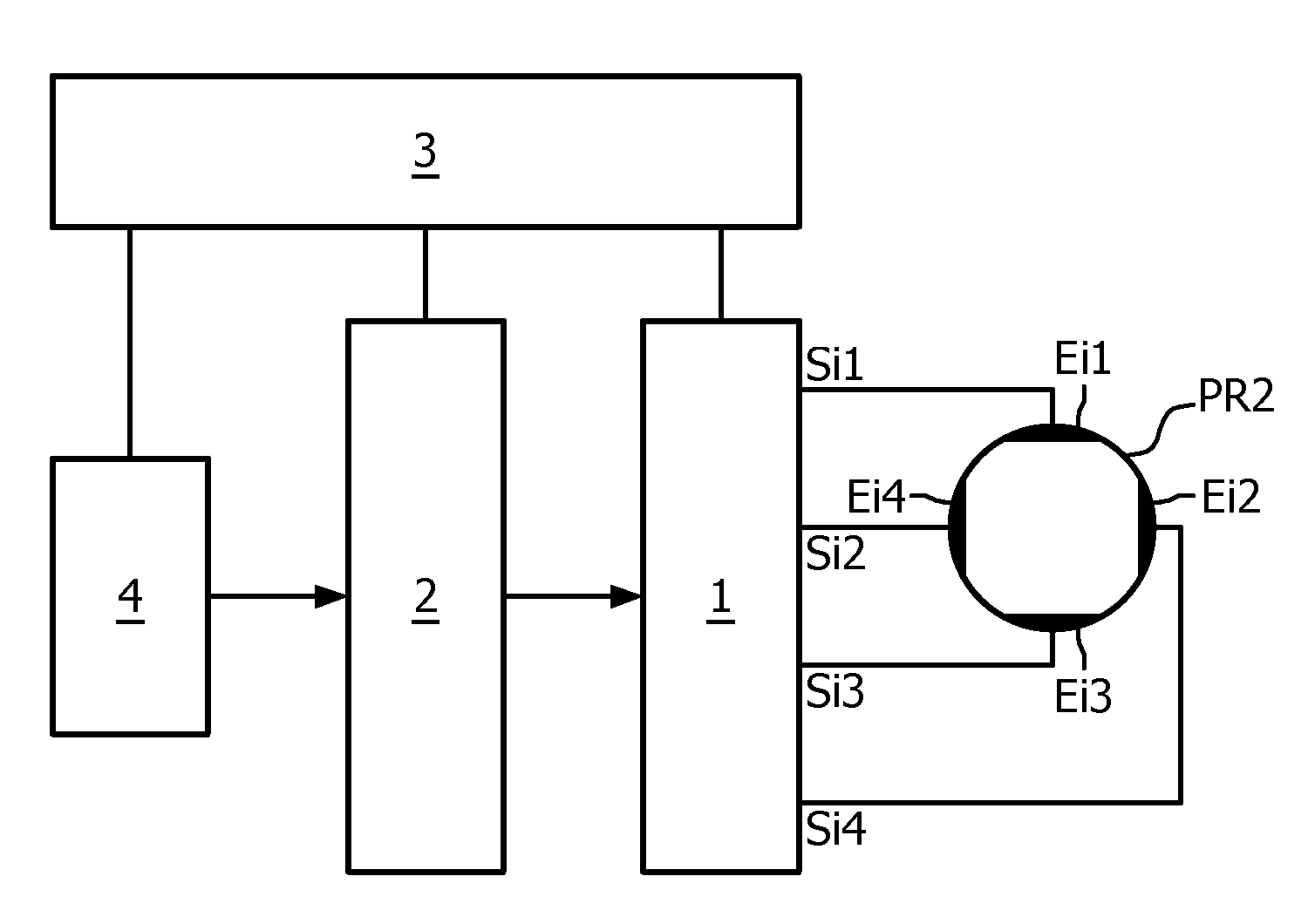
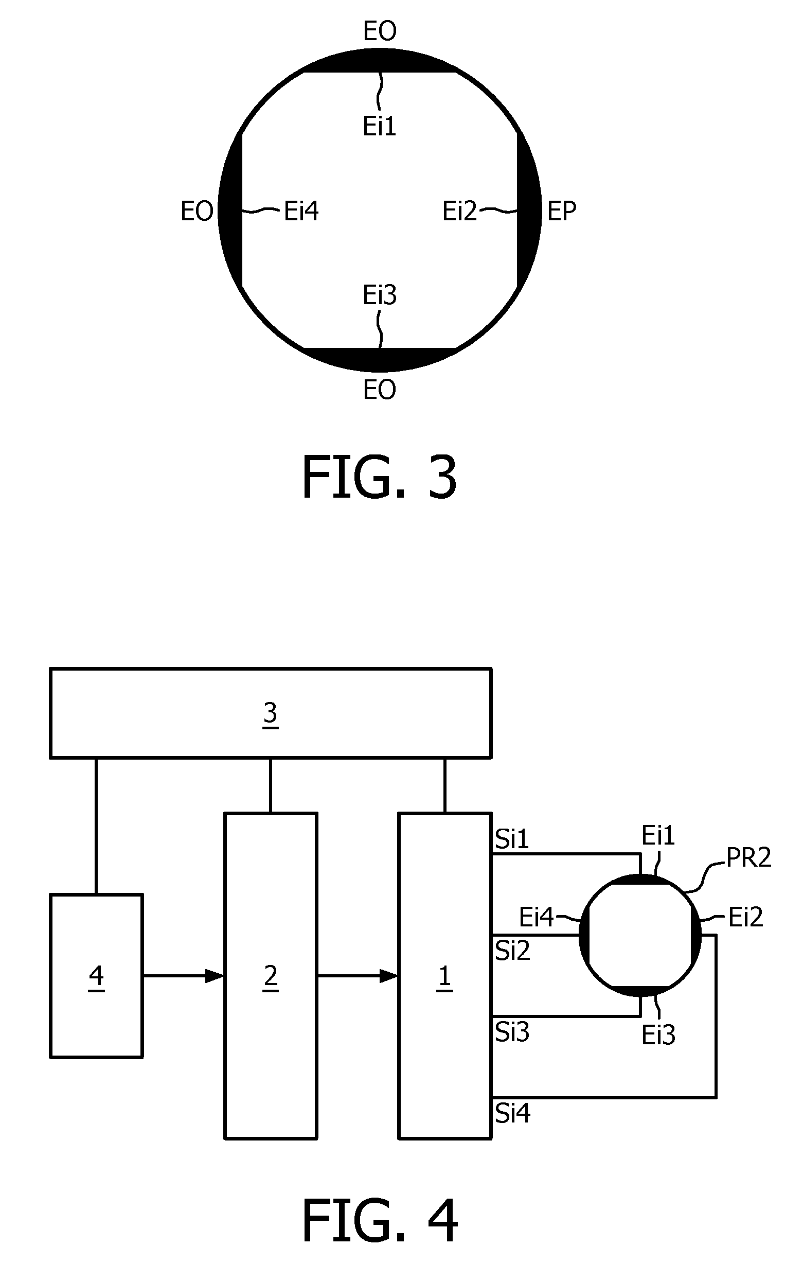
[0013]A system for providing an electrical stimulus to surrounding tissue in accordance with the first aspect of the invention comprises a probe with multiple electrodes. A generator supplies electrical signals to the electrodes to obtain a field distribution in the surrounding tissue. A controller which controls the generator provides in a first state a first distribution of the electrical signals to the electrodes to generate a first field distribution, and in a second state a second distribution of the electrical signals to the electrodes to generate a second field distribution. The first distribution of electrical signals is more symmetrical with respect to the electrodes than the second distribution of electrical signals, and a total amount of electrical stimulation currents caused by the electrical signals in the second state is lower than in the first state. By having a total amount of currents which is less in a more asymmetrical distribution, it is possible to prevent a too large increase of the power drawn by the system. Especially if the power to the system is supplied by a battery, a too large power drain would cause a battery to be depleted too fast. The other way around, if the distribution of the electrical signals is selected to be more symmetric or is changed into a more symmetric distribution, it is allowed to increase the total amount of currents without causing the battery to be drained too fast.
[0017]In an embodiment, the controller reduces the total amount of electrical stimulation currents when changing from the first state into the second state in such a manner that the total power supplied to the electrodes in the first state and in the second state is kept substantially constant. In this manner, the power drawn from the battery is kept substantially constant and an undesirable fast depletion of the battery is prevented. For example, dependent on the desired life time of the battery, the current may not be allowed to increase more than 25% or even not more than 5%.
[0018]In an embodiment, the controller reduces the total amount of electrical stimulation currents to keep the field distribution in the second state within borders of the field distribution in the first state. In another embodiment, the controller reduces the total amount of electrical stimulation currents such that a maximum of the field distribution in the second state is substantially equal to a maximum of the field distribution in the first state. The maximum of the field distribution is defined by trespassing a particular threshold of the field strength. Thus, the electrical stimulation currents are controlled in such a way that the strength of the field in the second state is nowhere larger than the strength of the field in the first state, only the directivity changes.

Problems solved by technology

Especially if the power to the system is supplied by a battery, a too large power drain would cause a battery to be depleted too fast.

Method used


Image

  • High Resolution Electrical Stimulation Leads
  • High Resolution Electrical Stimulation Leads
  • High Resolution Electrical Stimulation Leads

Examples


Embodiment Construction

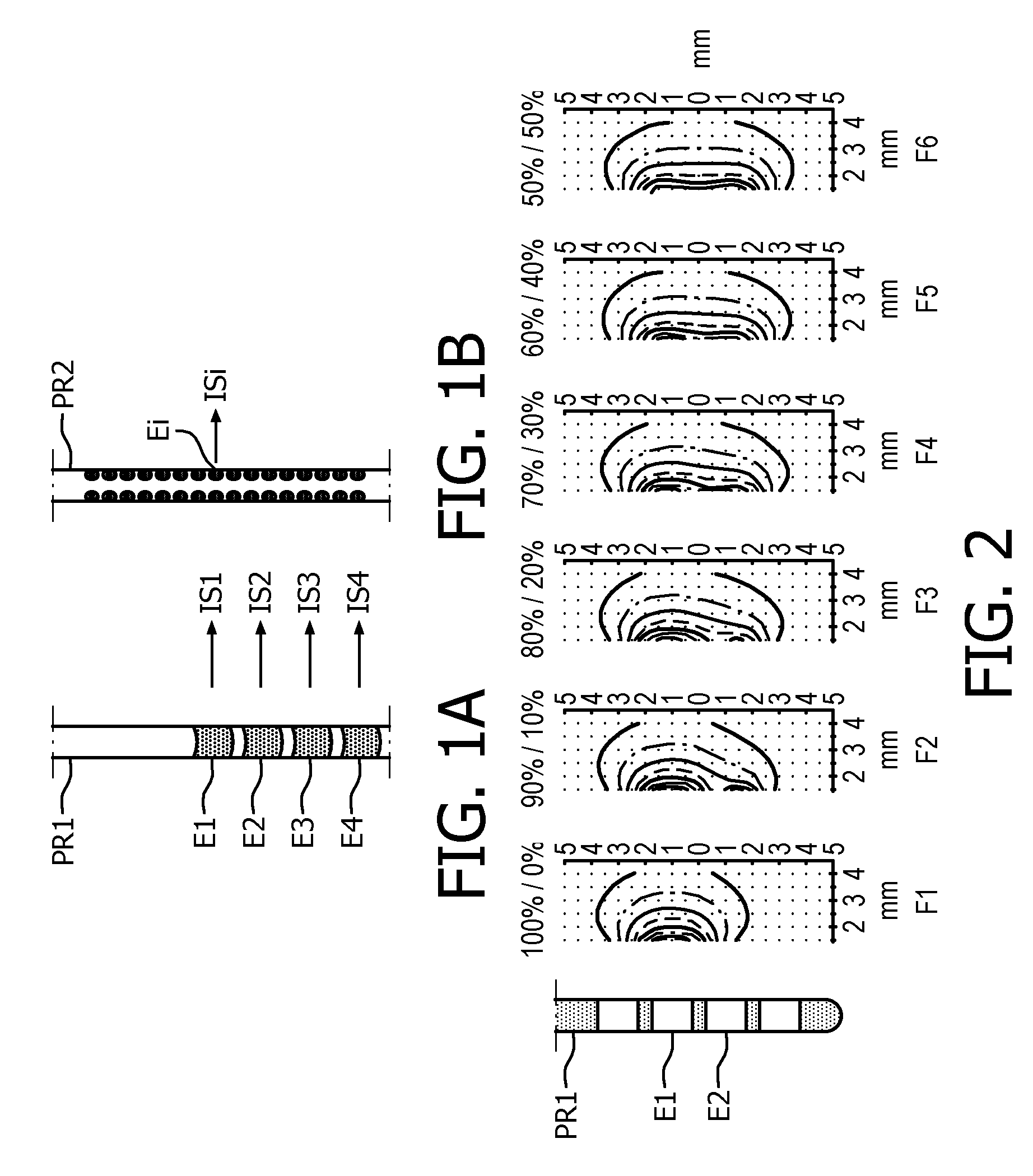
[0035]FIG. 1A shows a state-of-the-art low resolution DBS lead, and FIG. 1B shows a state-of-the-art high-resolution DBS-array. Both DBS probes are elongated cylindrical support structures on which the electrodes Ei are indicated by black areas.

[0036]In FIG. 1A, of the low resolution DBS lead PR1, four electrodes E1 to E4 are shown which are arranged circumferential on the support structure. The low resolution DBS lead PR1 may have fewer or more than four electrodes E1 to E4. When driven, these electrodes E1 to E4 supply electrical stimulation currents IS1 to IS4, respectively to the surrounding tissue. The electrodes are collectively also referred to by Ei and the electrical stimulation currents are collectively also referred to by ISi.

[0037]In FIG. 1B, a high resolution DBS-array PR2 is shown in which groups of four electrodes Ei are axially displaced along the support structure. The four electrodes Ei are equidistantly positioned around the circumference of the support structure....


PUM


Abstract

System for providing a stimulus comprising a probe with multiple electrodes each capable of providing a particular current to surrounding tissue a generator for providing to each of the electrodes the particular current a controller for controlling the generator to provide current to the electrodes to achieve a desired electrical field around the probe.

Description

FIELD OF THE INVENTION[0001]The invention relates to a system for providing an electrical stimulus to surrounding tissue, and a method of providing an electrical stimulus to surrounding tissue.BACKGROUND OF THE INVENTION[0002]New high resolution neural interfaces allow for accurate spatial steering of therapeutic stimulation towards target tissue. Such high-resolution interfaces usually comprise an array-like distribution of elements (e.g. contacts or electrodes) capable of delivering stimuli (e.g. electrical pulses) and the array is usually placed on a carrier structure (e.g. an elongated flexible probe). FIG. 1B presents an example of such a high resolution neural interface used for the accurate delivery of electrical stimulation for the purpose of deep brain stimulation therapy. For comparison is provided in FIG. 1A on the same scale a conventional low-resolution neural interface for deep brain stimulation therapy. The electrodes shown in FIGS. 1A and 1B are also referred to as s...

Claims


Application Information

Patent Timeline
IPC IPC(8): A61N1/36
CPCA61N1/0534A61N1/36182A61N1/36185A61N1/36082
Inventor MARTENS, HUBERT CECILE FRANCOISDECRE, MICHEL MARCEL JOSETOADER, EMIL-CODRUT
Owner MEDTRONIC BAKKEN RES CENT
Learn More