Method of multi-carrier communication

Inactive Publication Date: 2012-11-01
ALCATEL LUCENT SAS
View PDF2 Cites 5 Cited by
  • Summary
  • Abstract
  • Description
  • Claims
  • Application Information

AI Technical Summary

Benefits of technology

[0013]According to the second preferred aspect of the invention, the predetermined protocol layer is the radio link control layer. the generating step further comprises the following steps: Obtaining communication resources provided by each carrier respectively, from the medium access control layer; According to the communication resources provided by each carrier respectively, for each logical channel, based on a certain principle, selecting at least one carrier to transmit the data section of the data transmitting the logical channel, wherein, the certain principle is to minimize the times for which the data of each logical channel is divided to be transmitted on multiple carriers. For each logical channel, generating at least one data unit of radio link con o layer respectively corresponding to at least one carrier, transmitting the data section of the logical channel, as the middle block, the data unit comprises the data section of the data of the logical channel allocated to the carrier for transmitting; and when the data of the logical channel are allocated to multiple component carriers, each data unit comprises the location information of the data section in the complete data of the logical channel. The creating step, for each carrier respectively, uses a merge of at least two data units or uses one data unit corresponding to the carrier, to create the protocol unit of the carrier. The preferred aspect reduces the occurrence that the data section of LCH transmits in multiple carriers, so the head overhead generated from RLC, MAC layer is less.
[0017]The preferred aspect only needs that the MAC layer implements adaptive adjustment for the carrier aggregation, using RLC PDU for carrier mapping; while the PLC layer still generates a RLC PDU for each LCH according to the provision of R8, not requiring any change for the RLC layer. And the preferred aspect reduces the occurrence that the data of LCH is divided into multiple sections, thus the overhead of head is less.

Problems solved by technology

So in current standard there is no solution of the technical issue on how to map the data of each LCH buffered in radio link control (RLC) layer to different CC for communication.

Method used


Image

  • Method of multi-carrier communication
  • Method of multi-carrier communication
  • Method of multi-carrier communication

Examples


first embodiment

The First Embodiment

[0027]The embodiment maps the data of LCH to multiple CC in the RLC layer.

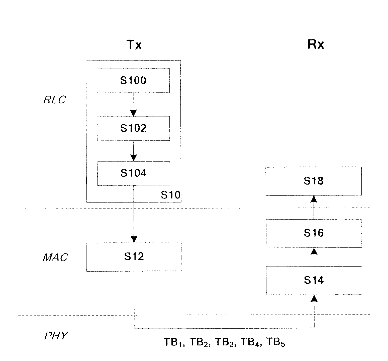
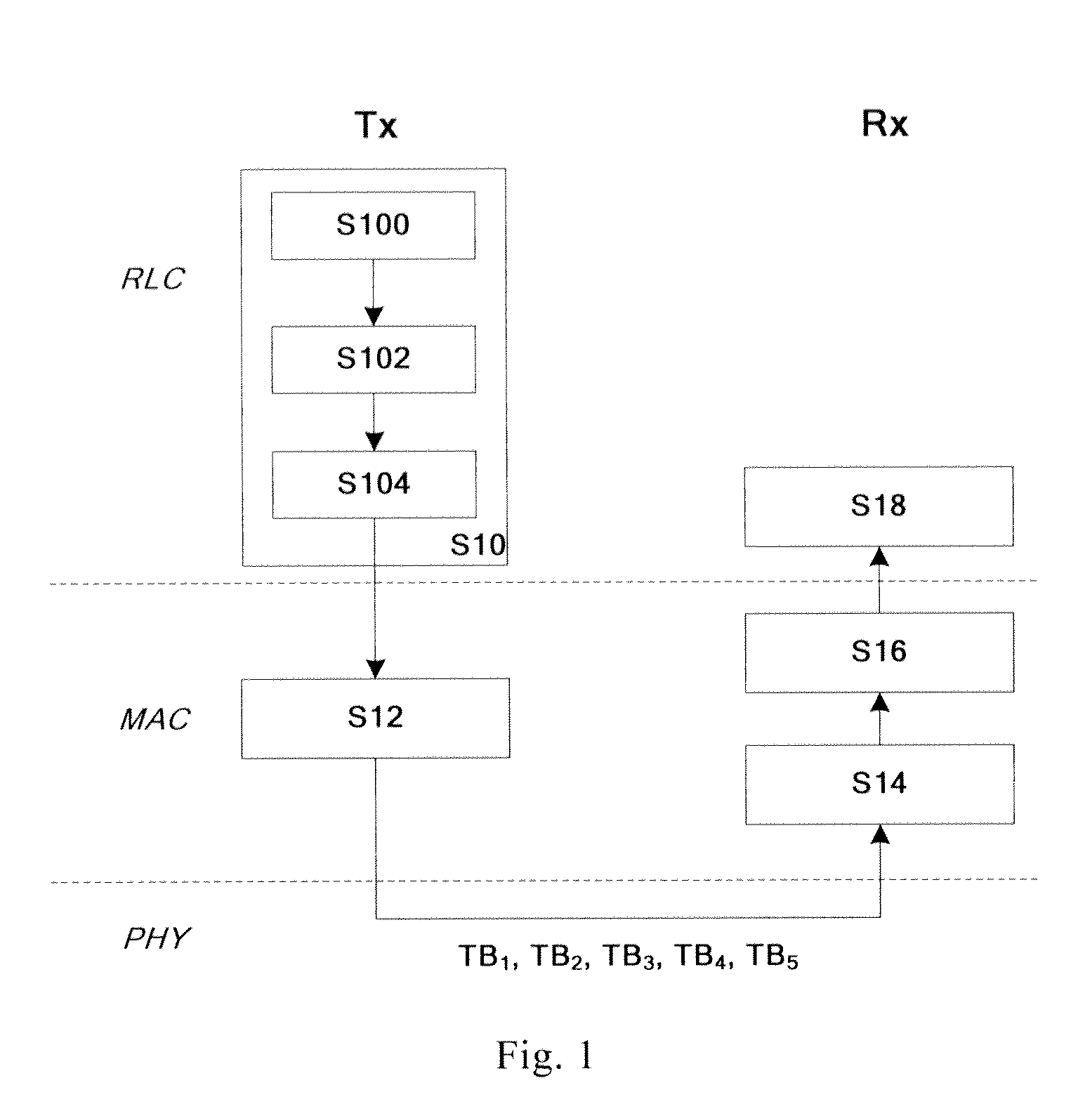
[0028]As shown in FIG. 1, first, step S10, in the RLC layer of transmitter Tx, generates respectively for each LCH, at least one middle block transmitted in at least one carrier, each of the at least one middle block comprises each data section of data of each logical channel transmitted in each carrier;

[0029]In detail, in step S100, the RLC layer obtains communication resources provided by each component carrier respectively, from the medium access control (MAC) layer;

[0030]Next, in step S102, independently to each carrier in order, according to communication resources provided by the carrier, the RLC layer allocates the unallocated data of LCH to the carrier based on defined principles. In detail, five CC are taken as examples to describe, which is CC1, CC2, CC3, CC4 and CC5.

[0031]First, using the component carrier CC1, according to the priority order of LCH, allocating minimum amount of ...

second embodiment

The Second Embodiment

[0048]The embodiment maps the data of the LCH to multiple CC in the RLC layer.

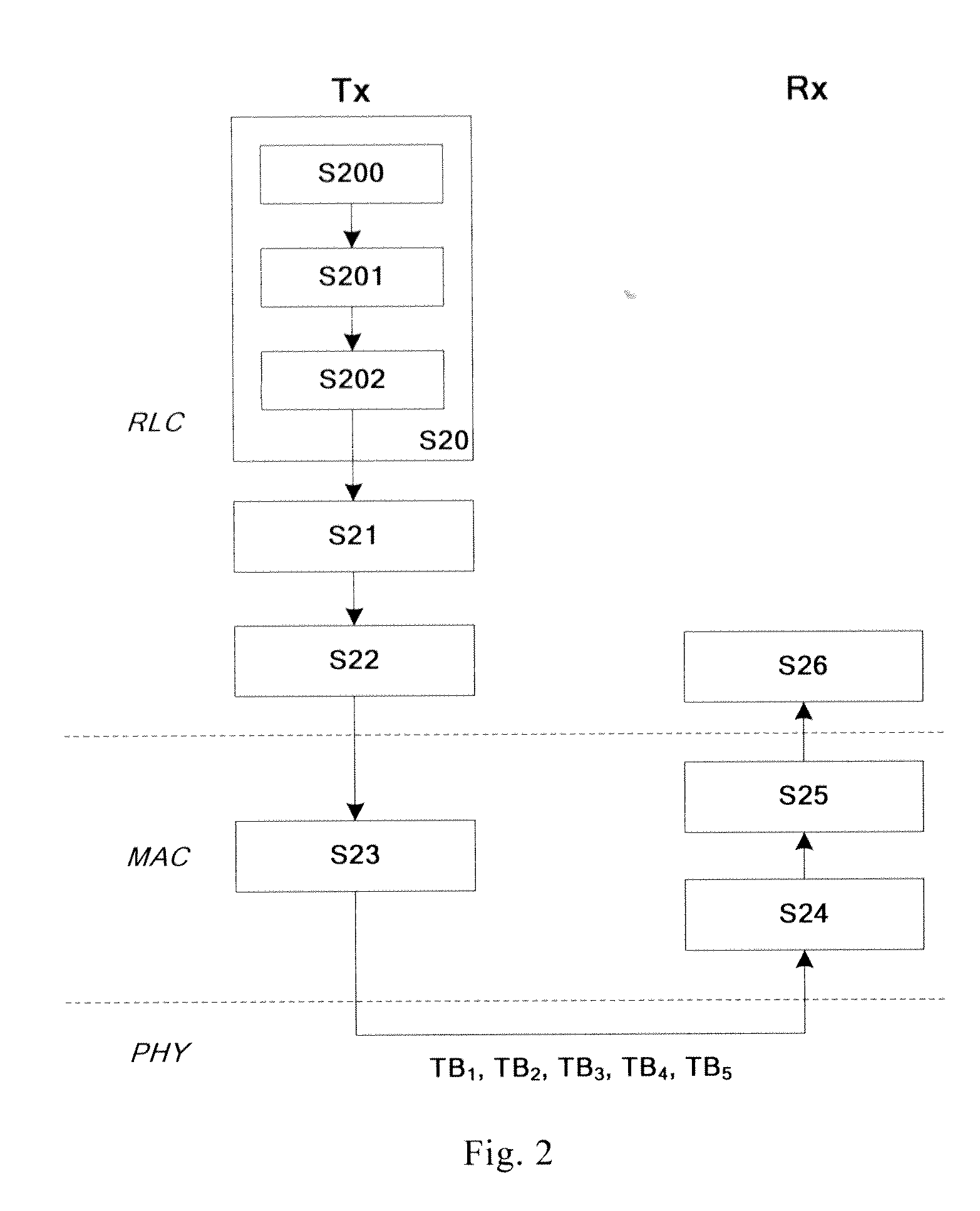
[0049]Before mapping the data of each LCH to CC, preferably, the RLC layer determines the amount of data of each LCH transmitting in the TTI respectively. As shown in FIG. 2, in the step S20, the RLC layer calculates the amount of the data of each LCH mapped to CC.

[0050]In a preferred embodiment, the RLC layer calculates the amount of the data of each LCH mapped to CC according to the priority of each LCH.

[0051]First, in the step S200, the RLC layer obtains from the MAC layer the total communication resources provided by each CC.

[0052]After that, in the step S201, according to the total communication resources and the priority order of each LCH, the RLC layer allocates minimum amount of transmitted data to be transmitted of each LCH, until the communication resources are exhausted, or all of the minimum amount of transmitted data of each LCH are allocated.

[0053]If all of the minimum am...

third embodiment

The Third Embodiment

[0070]The embodiment maps the data of LCH to multiple CCs in the MAC layer.

[0071]Before the data of each LCH is mapped to CCs, preferably, the RLC layer decides the amount of data each LCH transmitting in the TTI respectively. Similar with the second embodiment, as shown in FIG. 3, in the step S30, the RLC layer calculates the amount of the data of each LCH mapped to CC.

[0072]In a preferred embodiment, the RLC layer calculates the amount of the data of each LCH mapped to CC according to the priority of each LCH.

[0073]First, in the step S300, the RLC layer obtains the total communication resources provided by each CC from the medium access control (MAC) layer.

[0074]After that, in the step S301, according to the total communication resources and the priority order of each LCH, the RLC layer allocates minimum amount of transmitted data to be transmitted of each LCH, until the communication resources are exhausted, or all of the minimum amounts of transmitted data of...


PUM


Abstract

In order to provide a technical solution of mapping data to multiple carrier, the invention proposes a method of multi-carrier communication. The transmitter Tx, in the predetermined protocol layer, generates respectively for each LCH, at least one middle block transmitted in at least one carrier, each of the middle block is comprised in each data section of data of each LCH transmitted in each carrier; In the MAC layer, for each carrier, generates a MAC PDU, the MAC PDU comprising each middle block transmitted in the carrier and the identification information of the LCH to which the MAC PDU belongs. The receiver Rx, in the MAC layer, receives each MAC PDU corresponding to each carrier; in the predetermined layer, for each LCH respectively, recombines each middle block of the LCH to obtain the complete data of the LCH, according to the identification information of the LCH to which each middle block belongs. The predetermined layer can be RLC layer or MAC layer.

Description

TECHNICAL FIELD[0001]The invention relates to wireless communication, especially relate to multi-carrier communication.BACKGROUND TECHNOLOGY[0002]At present, the multi-carrier communication technology studied and applied more and more widely. For example, the carrier aggregation (CA) is adopted as the major technology of LTE-A (advanced long term evolution) standard to increase system performance. According to the current standard, up to five component carriers (CC) can be supported by LTE-A standard with bandwidth of each CC up to 20 MHz. It has been agreed in the current standard that one transport block (TB) will be generated for each CC in non-MIMO case which means that up to five TB maybe generated in one transmission time interval (TTI) for LTE-A transmitter; and the receiver such as user equipment may receive up to five TB in one TTI at the same time.[0003]In this situation, in order to maximize the utilization rate of component carriers, the transmitter should be able to map...

Claims


Application Information

Patent Timeline
IPC IPC(8): H04W72/04
CPCH04W28/065H04W72/1263H04L5/0044H04L5/001H04L5/0007H04L5/02
Inventor YANG, TAO
Owner ALCATEL LUCENT SAS
Why Eureka
Try Eureka