
Head part of an annular combustion chamber

Active Publication Date: 2012-11-01
ROLLS ROYCE PLC
View PDF5 Cites 13 Cited by
  • Summary
  • Abstract
  • Description
  • Claims
  • Application Information

AI Technical Summary

Benefits of technology

[0017]The ring member may be machined to have a smooth surface for receiving the protruding portion of the burner collar. The ring member may comprise one or more openings. The openings may be adapted to minimise the weight of the ring member and / or provide cooling air, e.g. to the heat shield.

Problems solved by technology

It will be understood that the combustor parts of a gas turbine engine will generate significant heat and therefore thermal stressing as well as vibration and other factors may create significant wear upon the mountings for the spray nozzle.
This additional weight is disadvantageous particularly in the case of a jet engine gas turbine.

Method used


Image

  • Head part of an annular combustion chamber
  • Head part of an annular combustion chamber
  • Head part of an annular combustion chamber

Examples


Embodiment Construction

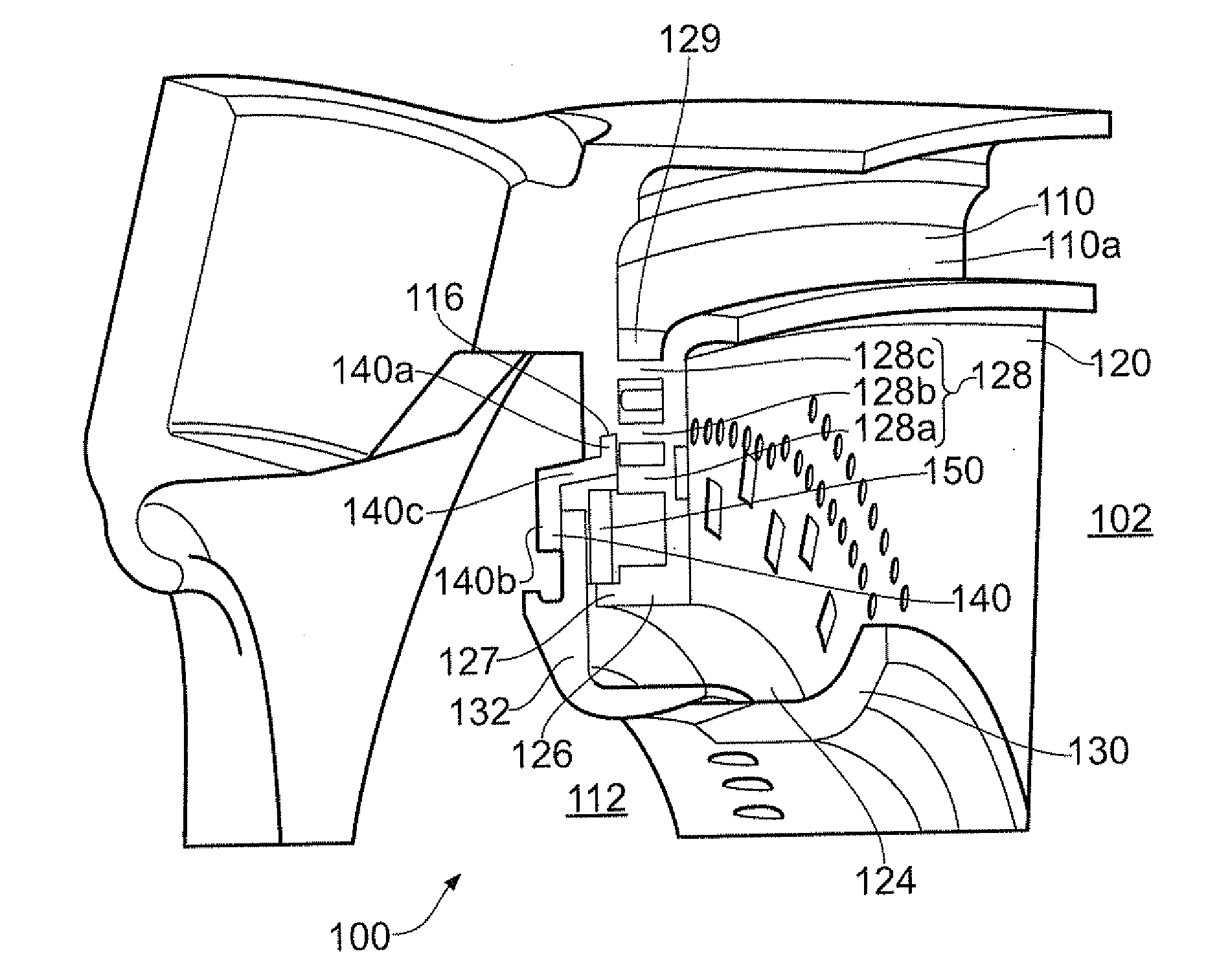
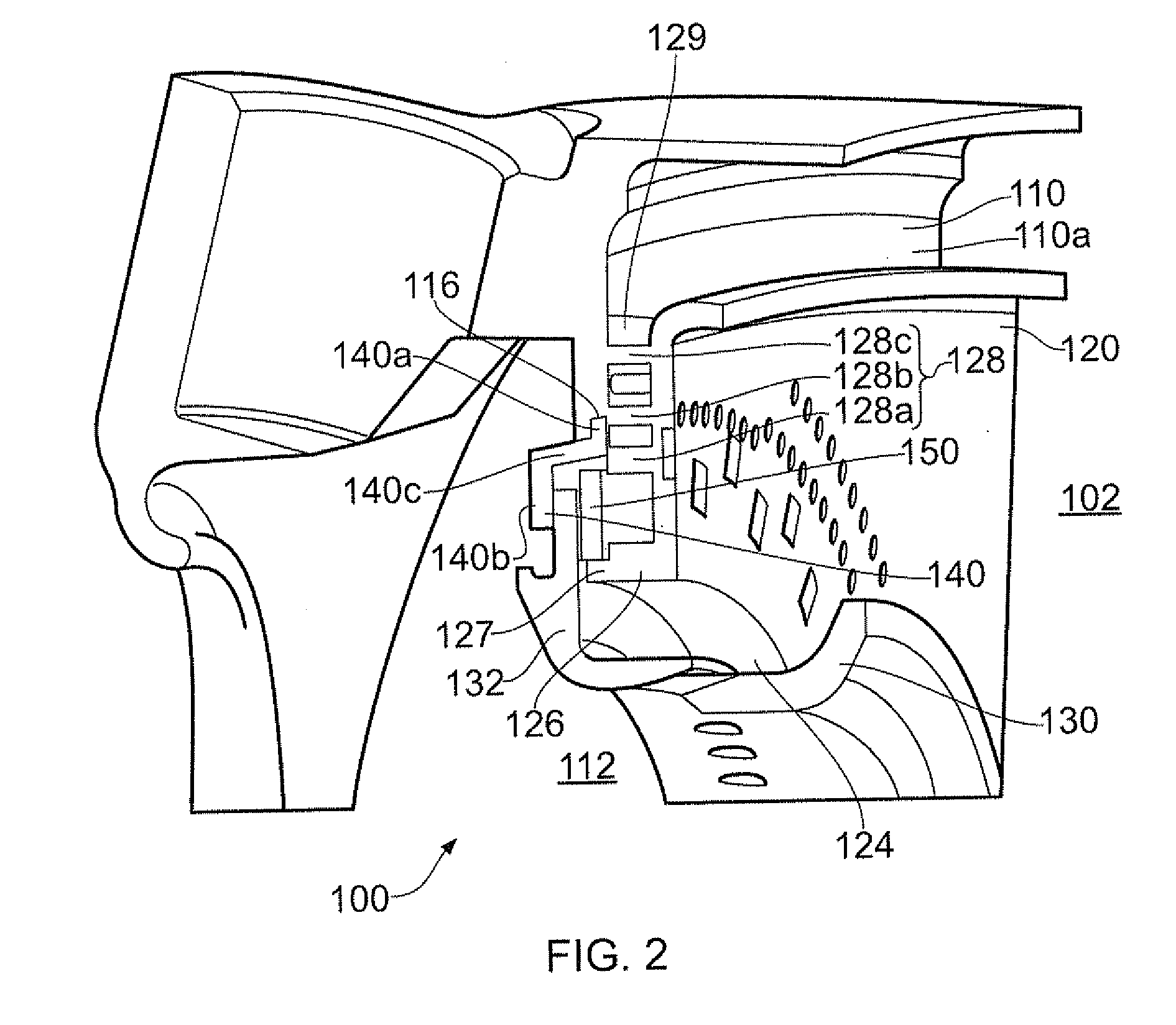
[0029]With reference to FIG. 2, a head part 100 of an annular gas turbine combustion chamber 102, according to an example of the present disclosure, may comprise an end wall or meter panel 110 which may act as a supporting and / or dividing wall for the combustion chamber 102 downstream of the end wall. The end wall 110 may comprise a passage opening 112 for accommodating a burner (not shown). The end wall 110 may comprise a substantially annular body disposed about a longitudinal axis of the gas turbine (not shown) and a plurality of burners may be provided equiangularly distributed about the end wall. To this extent, this annular combustion chamber corresponds to the known state of the art. Also in a known manner, several burners project in a circularly arranged manner into the annular combustion chamber, by way of which fuel as well as combustion air may be charged in a swirled manner into the combustion chamber.

[0030]The head part 100 may also comprise a heat shield 120 covering a...


PUM

PropertyMeasurementUnit
Weightaaaaaaaaaa
Diameteraaaaaaaaaa
Perimeteraaaaaaaaaa

Abstract

A head part of an annular combustion chamber for a gas turbine, the head part comprising: an end wall with a passage opening for accommodating a burner, the end wall comprising a back side which faces towards the combustion chamber; a burner collar adapted to fit within the passage opening and receive the burner, the burner collar comprising a protruding portion radially protruding from an outer surface of the burner collar; and a ring member for receiving the protruding portion of the burner collar; wherein the head part of the annular combustion chamber is configured such that in an installed configuration a radially outer portion of the ring member engages with the end wall and a radially inner portion of the ring member receives the protruding portion of the burner collar.

Description

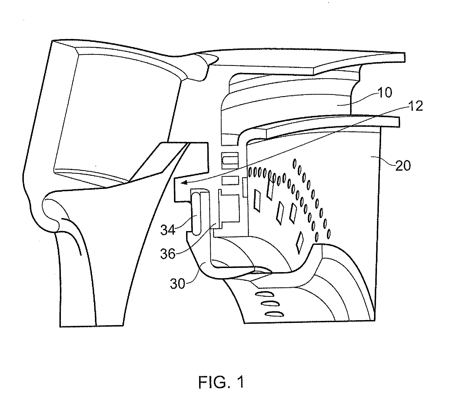
CROSS-REFERENCE TO RELATED APPLICATIONS[0001]This application is based upon and claims the benefit of priority from British Patent Application Number 1107090.1 filed 28 Apr. 2011, the entire contents of which are incorporated by reference.BACKGROUND OF THE INVENTION[0002]1. Field of the Invention[0003]The present disclosure relates to a head part of an annular combustion chamber and particularly but not exclusively relates to a head part of an annular combustion chamber for a gas turbine.[0004]The operation of gas turbine engines is relatively well known and, as will be appreciated, requires presentation of fuel for combustion in order to generate thrust. In order to present that fuel, a fuel spray nozzle or burner is required. A plurality of burners may be provided about the annulus of an annular combustion chamber.[0005]2. Description of the Related Art[0006]Referring to FIG. 1, which shows a previously-proposed arrangement, the fuel burner (not shown) is typically located within ...

Claims


Application Information

Patent Timeline
IPC IPC(8): F23R3/28B21D53/00F02C7/20
CPCF23R3/10F23R3/283F23R3/50Y10T29/49323F23R2900/00012F23R2900/03041Y02T50/675F23R2900/00005Y02T50/60
Inventor MILBURN, RICHARD G.
Owner ROLLS ROYCE PLC
Learn More