
System and method for constructing a carrier to interference matrix based on subscriber calls

a subscriber-based, carrier-to-interference technology, applied in the direction of transmission monitoring, wireless commuication services, electrical equipment, etc., can solve the problem that other methods cannot provide, and achieve the effect of reducing time and expens

Inactive Publication Date: 2012-10-25
CINGULAR WIRELESS II LLC
View PDF2 Cites 41 Cited by
  • Summary
  • Abstract
  • Description
  • Claims
  • Application Information

AI Technical Summary

Benefits of technology

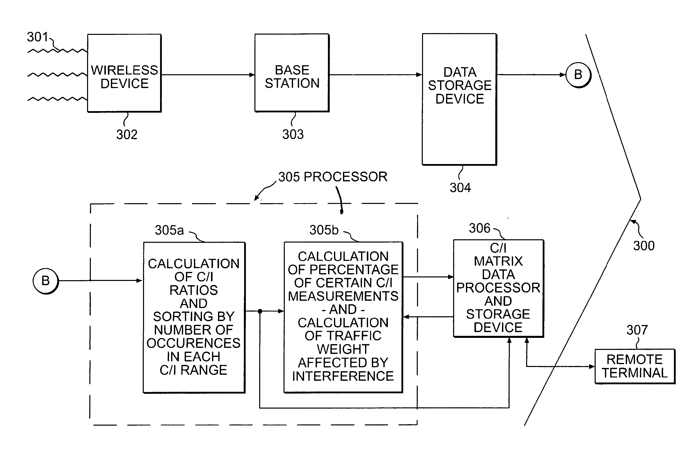
This automated system provides better statistical data, reduces costs, and ensures continuous monitoring of interference, enabling more effective frequency planning and improved service by using real-time, actual-use data from wireless devices across all geographic locations.

Problems solved by technology

Thus, an actual-use sampling of data is provided between wireless sites and sectors, something that other methods cannot provide.

Method used


Image

  • System and method for constructing a carrier to interference matrix based on subscriber calls
  • System and method for constructing a carrier to interference matrix based on subscriber calls
  • System and method for constructing a carrier to interference matrix based on subscriber calls

Examples


Embodiment Construction

[0030]A system or method in accordance with the present invention may serve various multi-technology wireless devices providing voice, data, video, or any other content. Further, the technologies employed may employ any transmission method including digital, analog or a combination of digital and analog. Therefore, the term wireless device as understood herein includes all devices capable of the wireless electronic communication of any type of data.

[0031]A system or method in accordance with the present invention may be implemented with hardware, firmware, software or a combination thereof. Both information storage and computations may be accomplished through an information processor and a memory device. These may be located within multiple network elements comprising a data processor, including but not limited to, a base station, a Mobile Switching Center (MSC), a Base Station Controller (BSC), an Operations Center (OC) or a separate system.

[0032]Referring now to the figures, where...


PUM


Abstract

A conventional wireless device constantly measures the signal strength of its server base station and the strength of signals from surrounding base stations for handoff purposes. The wireless device transmits this information to its serving base station, which discards the information a short time afterward, following handoff. The present system and method store the formerly discarded information in one of several existing network elements or in a separate computer system. This information is used to generate a carrier to interference ratio, which indicates the level of interference between station pairs, and to also generate a carrier to interference matrix, including identifying potential interference for each station pair. The frequency of occurrences during predetermined desired periods of time and the volume of traffic affected by each level of interference may also be calculated. This provides comprehensive, continuous, real-time information for wireless frequency planning.

Description

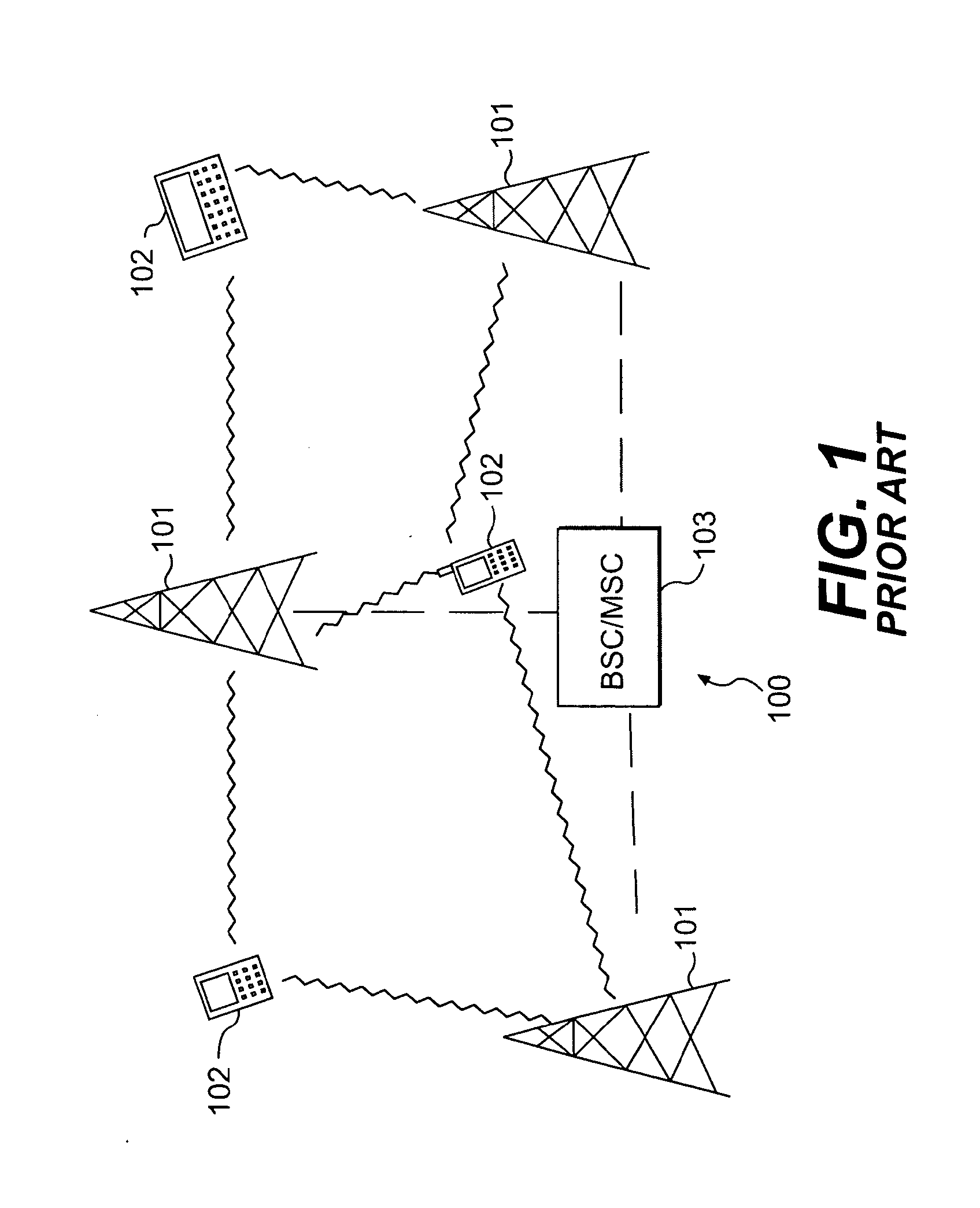
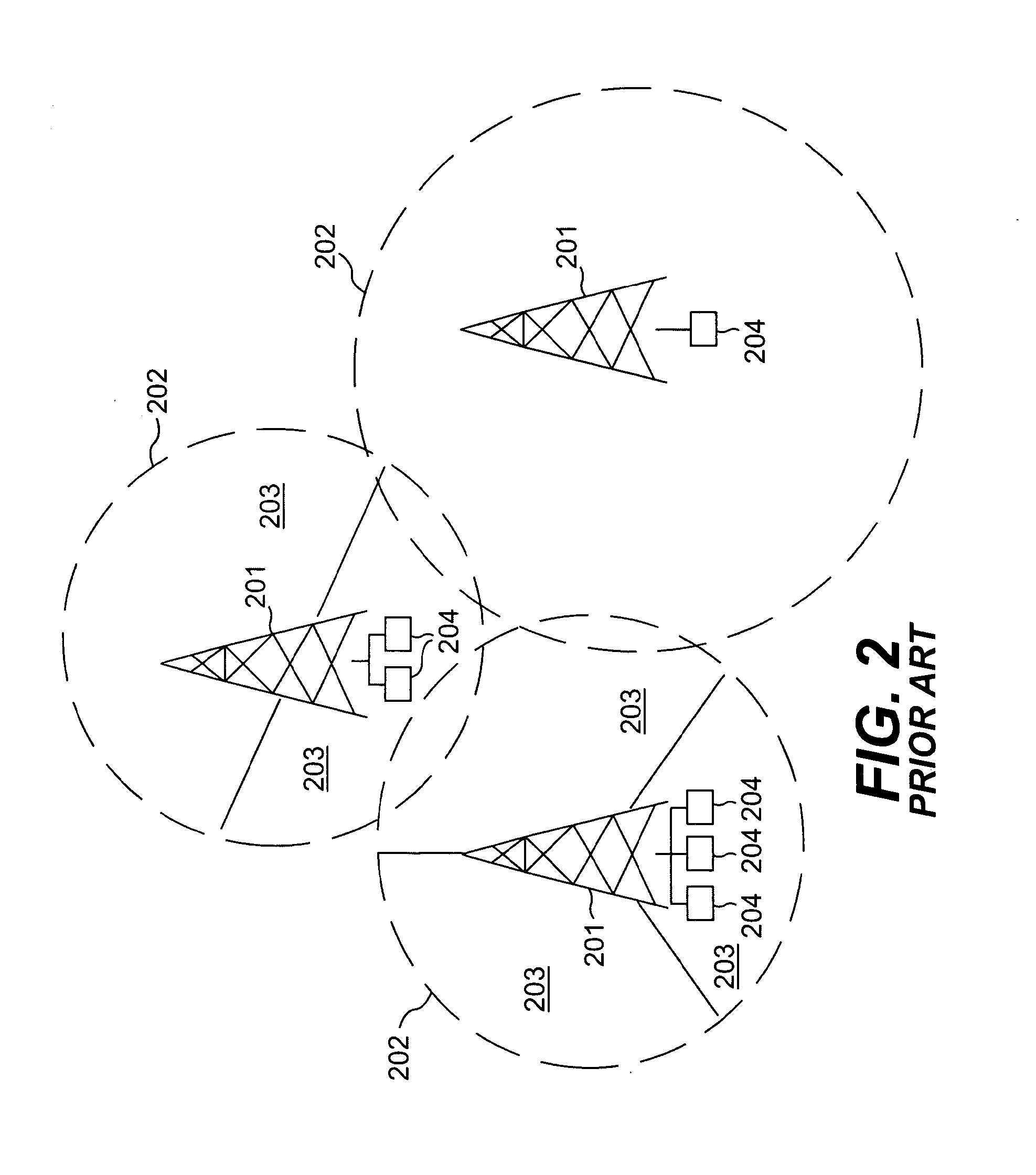
BACKGROUND OF THE INVENTION[0001]1. Field of the Invention[0002]The present invention relates to the field of frequency planning for wireless networks.[0003]2. Description of the Related Art[0004]As wireless subscribers travel, they are switched between different transmitter, or cell, sites. Each site may be divided into sectors, with each sector served by one or more base stations located at the transmitter site. A base station, or base transceiver station, comprises an antenna and a radio transceiver at the cell site. In order to accommodate as many users as possible, the base station is not in constant contact with each wireless device operating in its range. Instead, when a wireless device enters the coverage area of a cell, it contacts the server base station through a control channel. This control channel carries information between the wireless device and the server base station necessary for the wireless device to operate properly with the server base station. When a user in...

Claims


Application Information

Patent Timeline
Patent Type & Authority Applications(United States)
IPC IPC(8): H04W16/14H04W24/00
CPCH04W24/00H04W24/08H04B17/336H04W24/02H04B17/006
Inventor SHAH, DIPESH HASMUKHLAL
Owner CINGULAR WIRELESS II LLC
Learn More