
Ribbon microphone

a microphone and ribbon technology, applied in the field of ribbon microphones, can solve the problems of elongated state and significant deformation of performan

Inactive Publication Date: 2012-10-25
AUDIO-TECHNICA
View PDF0 Cites 8 Cited by
  • Summary
  • Abstract
  • Description
  • Claims
  • Application Information

AI Technical Summary

Benefits of technology

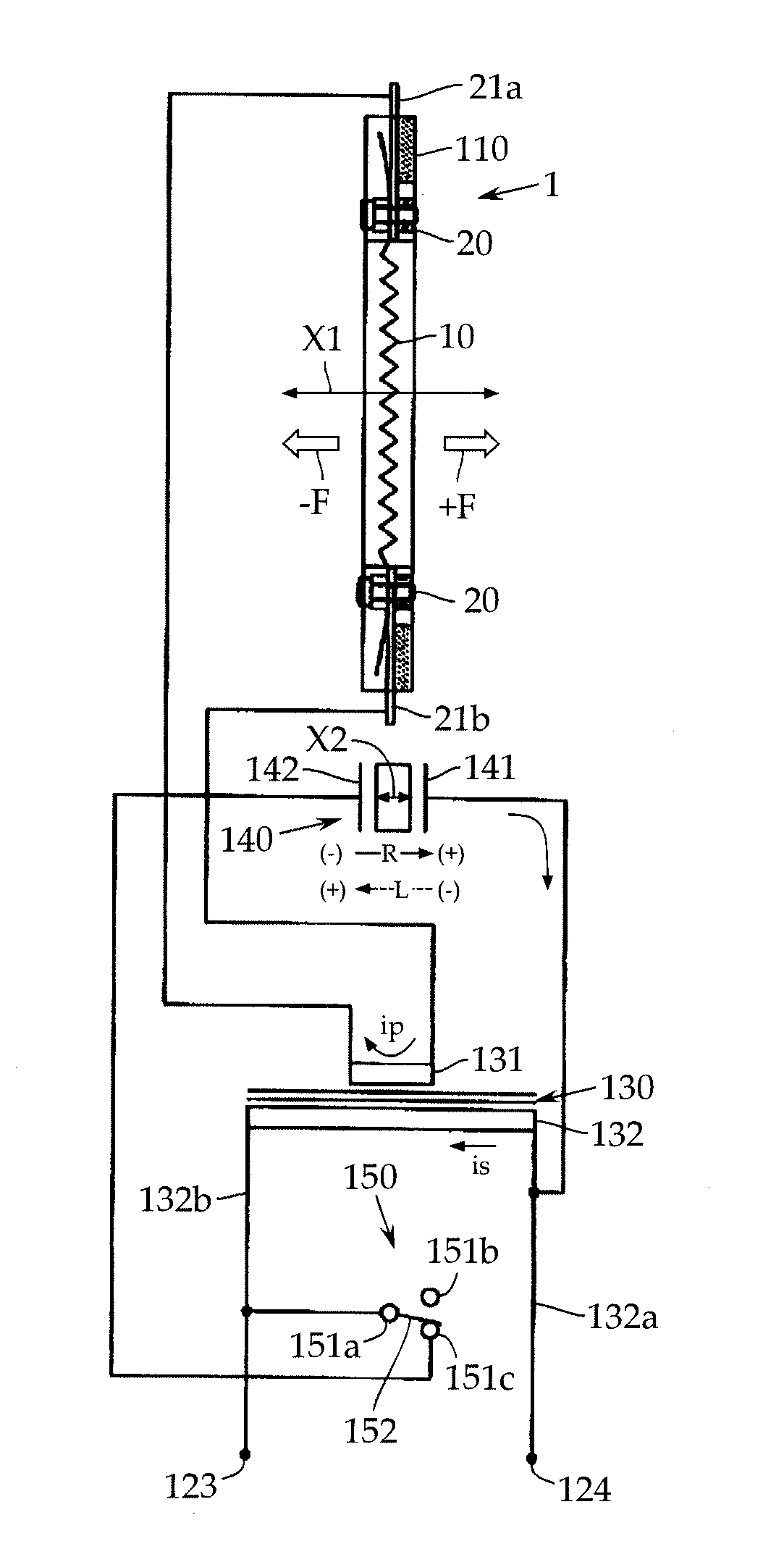
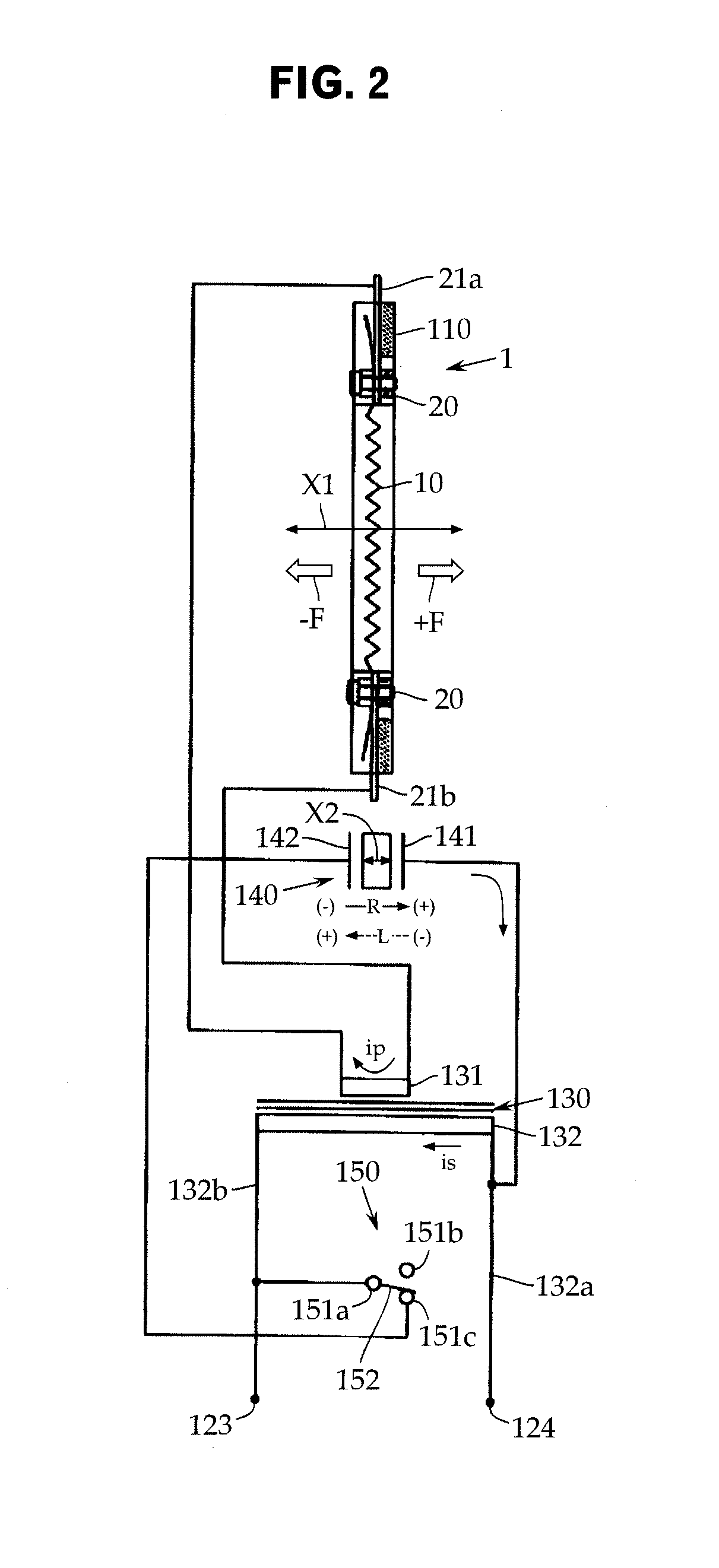
[0021]According to the invention, when the power plug of the phantom power supply is not connected and the microphone is not in use, the switching device connects both the electrodes of the piezoelectric element to the secondary winding of the step-up transformer. In this state, when an external impact causes the piezoelectric element to generate electric power, a current flows through the step-up transformer to the ribbon connected to the primary winding of the transformer so as to generate a driving force in the direction opposite to the direction in which the ribbon can be inertially displaced. In this way, the displacement of the ribbon can be suppressed within a range smaller than that achieved by the electromagnetic damping.

Problems solved by technology

A problem with a ribbon microphone is that, on impact against the microphone, an inertial force of the diaphragm (sometimes referred to as “ribbon” hereinafter) 10 stretches the ribbon foil, leaving it in an elongated state by plastic deformation.
When a ribbon plastic-deformed in this way contacts a magnetic pole or a nearby component, the performance may significantly be degraded.
Besides shocks during transportation, however, other shocks on impact against a microphone include a drop impact experienced, for example, when the microphone is accidentally dropped while being handled on a microphone stand for attachment.

Method used


Image

  • Ribbon microphone
  • Ribbon microphone
  • Ribbon microphone

Examples


Embodiment Construction

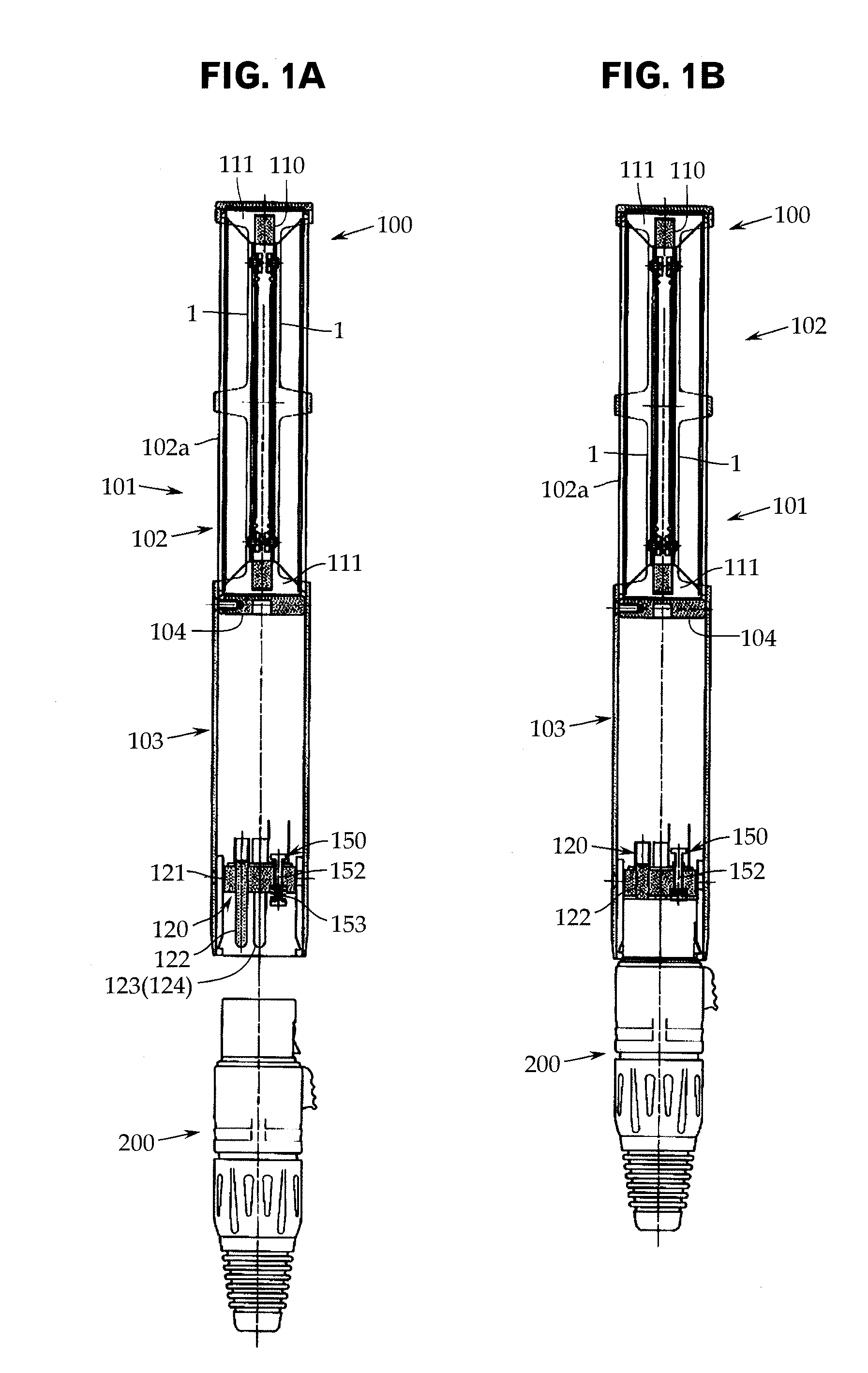
[0026]An embodiment of the invention will now be described with reference to FIGS. 1A, 1B and 2, although the present invention is not limited to the embodiment.

[0027]As shown in FIGS. 1A and 1B, a ribbon microphone 100 according to the embodiment is provided with a pair of acoustic-electric converters (i.e. microphone units) 1 having a ribbon foil, or a strip of foil, consisting of a metallic foil used as a diaphragm. The microphone is also provided with, as a casing, a cylindrical microphone case 101 made up of a sound-collecting section 102 and a case body 103 connected to each other via a connecting plate 104.

[0028]With reference to FIG. 3, the acoustic-electric converters 1 may each have a metallic foil such as an aluminum foil in the form of a strip of several micrometers thick as a diaphragm 10. The foil is placed in a parallel magnetic field formed by a pair of permanent magnets 30, 30 facing each other with a predetermined space therebetween.

[0029]In this embodiment, each a...


PUM


Abstract

To suppress the transverse displacement of a ribbon due to an impact to a level smaller than that achieved by electromagnetic damping. The switch 150 breaks a path between the piezoelectric element 140 and the secondary winding 132 so as to be non-conductive when a power plug is connected (the microphone is in use), and completes a path between the piezoelectric element 140 and the secondary winding 132 so as to be conductive when a power plug is not connected (the microphone is not in use), in order to generate a driving force in the direction opposite to the displacement direction of the ribbon 10 by causing a current corresponding to power generated in the piezoelectric element 140 to flow in the ribbon 10.

Description

CROSS-REFERENCE TO RELATED APPLICATION[0001]The present application is based on, and claims priority from, Japanese Application Serial Number JP2011-094154, filed Apr. 20, 2011, the disclosure of which is hereby incorporated by reference herein in its entirety.TECHNICAL FIELD[0002]The present invention relates to a ribbon microphone having a metallic ribbon foil used for a diaphragm, and in particular to a technique for protecting the diaphragm against shocks or the like.BACKGROUND ART[0003]As shown in FIG. 3, such a ribbon microphone is provided with an acoustic-electric converter (i.e. microphone unit) 1. The converter 1 has a metallic foil such as an aluminum foil in the form of a strip of several micrometers thick as a diaphragm 10. The foil is placed in a parallel magnetic field formed by a pair of permanent magnets 30, 30 facing each other with a predetermined space therebetween.[0004]Attachment electrodes 20, 20, which include a pair of support electrode plates 20a and 20b, a...

Claims


Application Information

Patent Timeline
IPC IPC(8): H04R17/02
CPCH04R9/08H04R9/048
Inventor AKINO, HIROSHI
Owner AUDIO-TECHNICA
Learn More