
Liquid droplet ejecting apparatus and liquid droplet ejecting method

a technology of liquid droplet ejection and ejection apparatus, which is applied in the direction of printing, other printing apparatus, etc., can solve the problems of increasing the operating cost of the device, the inability to accurately inspect the object, and the inability to change the bit map data, so as to prevent the decrease of printing speed and improve printing quality

Inactive Publication Date: 2012-10-25
SEIKO EPSON CORP
View PDF11 Cites 2 Cited by
  • Summary
  • Abstract
  • Description
  • Claims
  • Application Information

AI Technical Summary

Benefits of technology

[0011]For this reason, in the above mentioned publications, there is a waiting period in which ink cannot be ejected onto the target object while the nozzle ejecting states are being inspected to maintain good nozzle ejecting states, and printing speed has to be sacrificed for improved printing quality.
[0053]Thus, the invention according to the aspect as described above is able to improve printing quality while preventing a decrease in printing speed.

Problems solved by technology

An accurate inspection cannot be performed when subsequently ejected ink overlaps with previously ejected ink on the inspection ejection unit; therefore, subsequently ejected ink has to be ejected into a different region than previously ejected ink.
However, bit map data is not easy to change.
This increases the operating costs of the device.

Method used


Image

  • Liquid droplet ejecting apparatus and liquid droplet ejecting method
  • Liquid droplet ejecting apparatus and liquid droplet ejecting method
  • Liquid droplet ejecting apparatus and liquid droplet ejecting method

Examples


second embodiment

[0197]Next, a second embodiment of the present invention will be described. In this description, components similar to those in the first embodiment are either described simply or not at all.

[0198]FIG. 13 is a top view schematically illustrating the configuration of the liquid droplet ejecting apparatus 1A in the second embodiment of the present invention.

[0199]As shown in FIG. 10, the liquid droplet ejecting apparatus 1A in the present embodiment is equipped with a marking unit 81 for marking an edge of a recording medium 10.

[0200]When the marking unit 81 is arranged near the take-up reel 32, and an abnormality has been detected by the inspection unit 6 in the ink ejecting state of a nozzle 24, the edge of the recording medium 10 is marked correspondingly with respect to the region in which ink was ejected from the nozzle 24 in which an abnormality was detected.

[0201]The marking unit 81 makes a mark on the outside (that is, on the edge) of the region in which a drawing pattern is f...

third embodiment

[0204]Next, a third embodiment of the present invention will be described. In this description, components similar to those in the first embodiment are either described simply or not at all.

[0205]FIG. 14 is a top view schematically illustrating the inspection ejection unit 61A and the inspection scanner 62A in the liquid droplet ejecting apparatus in the third embodiment of the present invention.

[0206]As shown, the length of both the inspection ejection unit 61A and the inspection scanner 62A in the liquid droplet ejecting apparatus in the present embodiment is half that of the head unit 21.

[0207]Even in a case in which such a configuration is adopted, the inspection ejection unit 61A in the liquid droplet ejecting apparatus of this embodiment can move. As a result, movement of the inspection ejection unit 61A allows ink to be ejected onto the inspection ejection unit 61A from all of the nozzles 24, and the ejected ink can be imaged using the inspection scanner 61B.

[0208]In a liquid...


PUM


Abstract

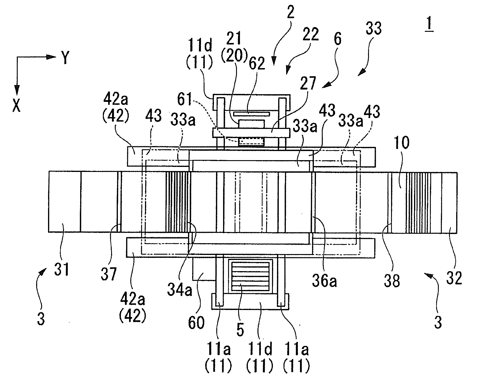
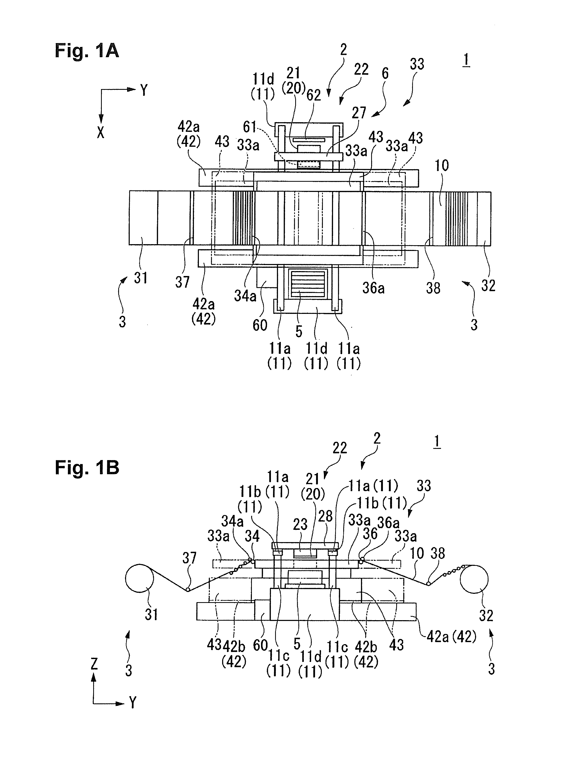
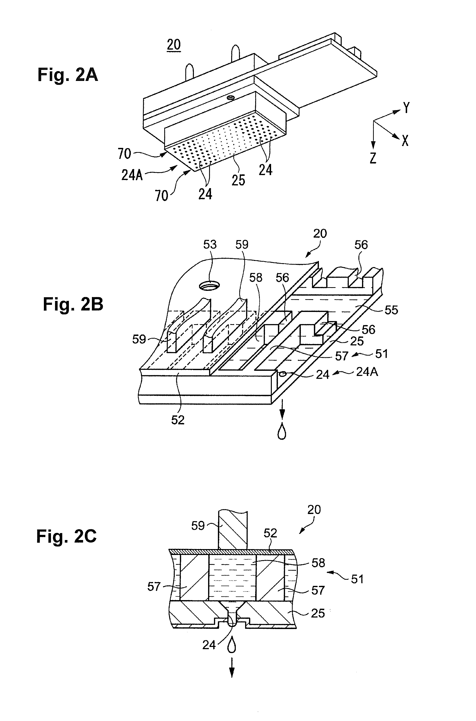
An inspection ejection unit is moved, and ink that has been ejected onto the inspection ejection unit is imaged in a region outside of a movable range of an ejecting head, whereby the ink ejecting state of the nozzle is inspected.

Description

CROSS-REFERENCE TO RELATED APPLICATIONS[0001]This application claims priority to Japanese Patent Application No. 2011-092744 filed on Apr. 19, 2011. The entire disclosure of Japanese Patent Application No. 2011-092744 is hereby incorporated herein by reference.BACKGROUND[0002]1. Technical Field[0003]The present invention relates to a liquid droplet ejecting apparatus and a liquid droplet ejecting method.[0004]2. Related Art[0005]A liquid droplet ejecting apparatus is equipped with an ejecting head in which ink-ejecting nozzles have been formed. By causing the ejecting head and a target object to move relative to one another, ink is ejected and arranged on the target object in a wide range.[0006]An inspection unit is installed in a liquid droplet ejecting apparatus of such description to inspect the ink ejecting state of the nozzles, for example, as shown in Japanese Laid-Open Patent Application No. 2006-76067 and Japanese Laid-Open Patent Application No. 2009-255086.[0007]In a case ...

Claims


Application Information

Patent Timeline
Patent Type & Authority Applications(United States)
IPC IPC(8): B41J29/38B41J2/16
CPCB41J2/16579
Inventor KOJIMA, KENJI
Owner SEIKO EPSON CORP
Learn More