
Modular multi-channel coil array for an MRI having decoupling of next but one neighbors

a multi-channel coil array and module technology, applied in the field of multi-channel coil arrays, can solve the problems of plurality of carriers, high cost, and device not being suited to realizing three-dimensional structures,

Active Publication Date: 2012-10-25
ALBERT LUDWIGS UNIV FREIBURG
View PDF6 Cites 10 Cited by
  • Summary
  • Abstract
  • Description
  • Claims
  • Application Information

AI Technical Summary

Benefits of technology

[0012]In contrast thereto, it is the underlying purpose of the present invention to modify a mufti-channel coil array of the described type in the technically simplest way possible such that tedious and expensive matching among the coils can be omitted and as many coil elements as possible are decoupled from each other. The space required for adding new coils should additionally be reduced. Any 3-dimensional or 2-dimensional shape can be easily realized through modular construction.

Problems solved by technology

This device, however, is not suited for realizing three-dimensional structures.
This is disadvantageous in that a plurality of carrier elements are necessary for adding one coil, the carrier elements each comprising further coil elements that are not required.
In this device, decoupling of the individual coils is moreover sensitive to displacements, for which reason they are not suited for mounting to flexible carrier elements.
This process is extremely tedious and therefore expensive for the mufti-channel coil arrays published up to now, of which some have more than 128 individual coils.

Method used


Image

  • Modular multi-channel coil array for an MRI having decoupling of next but one neighbors
  • Modular multi-channel coil array for an MRI having decoupling of next but one neighbors
  • Modular multi-channel coil array for an MRI having decoupling of next but one neighbors

Examples


Embodiment Construction

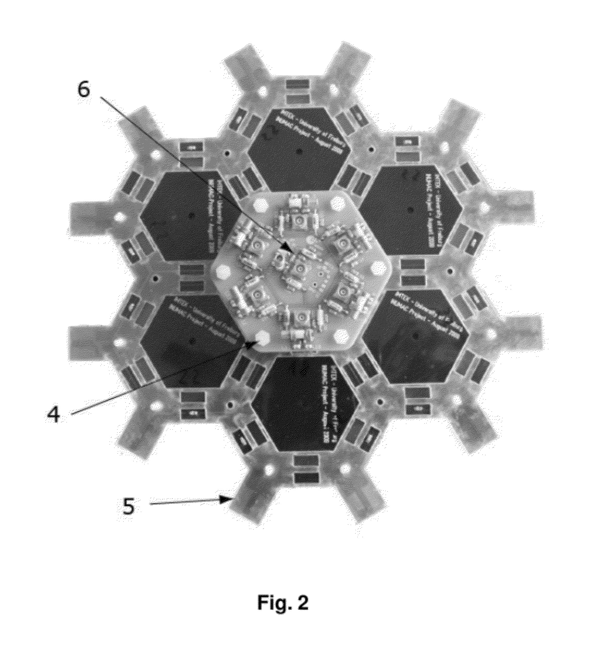
[0016]In one particularly preferred embodiment of an inventive multi-channel coil array, the carrier elements and individual coils have a hexagonal shape, which enables particularly tight covering of 2-dimensional structures.

[0017]In one further embodiment of an inventive mufti-channel coil array, the carrier elements and individual coils have a pentagonal shape. This is particularly advantageous in combination with the hexagonal carrier elements and individual coils in order to obtain three-dimensional structures, such as e.g. spheres.

[0018]Further embodiments of an inventive multi-channel coil array have carrier elements and individual coils with triangular or square shapes. This is advantageous in order to form further 2-dimensional or 3-dimensional shapes such as e.g. pyramids or cubes.

[0019]One particularly advantageous embodiment of the inventive multi-channel coil array is characterized in that individual coil elements of neighboring coils overlap, which minimizes the mutual ...


PUM

PropertyMeasurementUnit
Angleaaaaaaaaaa
Lengthaaaaaaaaaa
Sizeaaaaaaaaaa

Abstract

A multi-channel coil array for use as a transceiver in magnetic resonance imaging (MRI) has a plurality of radio frequency (RF) coils disposed next to one another, devices for electromagnetically decoupling the RF coils and coil elements which are applied onto a planar carrier element (5). The carrier elements (5) have a regular, equilateral polygonal outer contour and the shape of the individual coils (2) corresponds to the outer contour of the carrier element (5). An individual coil (2) has a loop-shaped structure (1), which leads to a decoupling of individual coils (2) not immediately adjacent to each other when a plurality of individual elements are arranged. The space requirement for adding new coils is reduced, and the modular design makes it possible to easily implement any three-dimensional or two-dimensional shape.

Description

BACKGROUND OF THE INVENTION[0001]The invention relates to a multi-channel coil array for use as a transmitting and / or receiving element in magnetic resonance tomography (MRT), comprising a plurality of radio frequency (RF) coils disposed next to one another, wherein devices for electromagnetically decoupling the RF coils are provided, wherein coil elements are mounted to a planar carrier element, which each form an individual element together with the carrier element, wherein the carrier elements have a regular equilateral polygonal outer contour and wherein a 2-dimensional or 3-dimensional structure of the entire coil array is created by joining a plurality of individual elements to each other, wherein the coil elements are arranged on each carrier element such that they result in a complete individual coil (2), respectively, and wherein the individual coils (2) have a shape that corresponds to the outer contour of the carrier element (5).[0002]A device of this type is disclosed in...

Claims


Application Information

Patent Timeline
IPC IPC(8): G01R33/3415H01F7/06
CPCG01R33/34007Y10T29/49071G01R33/365G01R33/3415
Inventor PETER, ANDREASSCHONHARDT, STEFANKORVINK, JAN
Owner ALBERT LUDWIGS UNIV FREIBURG
Learn More