
Compact force sensor for catheters

Active Publication Date: 2012-10-18
ST JUDE MEDICAL INT HLDG SARL
View PDF6 Cites 68 Cited by
  • Summary
  • Abstract
  • Description
  • Claims
  • Application Information

AI Technical Summary

Benefits of technology

[0018]Leo '789 discloses a force sensor that, through the matching of the coefficient of thermal expansion (CTE) of structural members with the CTE of the fiber optics, is substantially insensitive to temperature change. Leo '789 also discloses configurations of the force sensor that mechanically amplifies the detected deflection due to an applied distal end force, thus increasing the sensitivity of the force sensor.
[0020]Embodiments of the invention disclosed herein provide the compactness of the Kistler device while reducing the thermally induced error. Some embodiments provide for a more uniform response between force sensing elements.
[0032]In another embodiment, a method of making a force sensor for a catheter comprises providing a structural member having a reflecting member and arranging a distal end of a fiber optic opposite the reflecting member. The fiber optic and the reflecting member define a distance therebetween, the distance being within a range of predetermined values and being responsive to a force exerted on the structural member. The reflecting member can have a coefficient of thermal expansion that compensates for changes in the distance between the fiber optic and the reflecting member that are caused by temperature changes to the structure and the reflecting member.

Problems solved by technology

However, due the materials of construction, the Kistler and Leo '418 devices are subject to greater thermally-induced error than the device of Leo '789.
The device disclosed by Kistler is also prone to unequal sensitivities between sensing elements, i.e., the displacement at one sensing element per unit force is different from that of another sensing element.
This can cause differing sensitivity and attendant uncertainty that depends on the direction of the force.

Method used


Image

  • Compact force sensor for catheters
  • Compact force sensor for catheters
  • Compact force sensor for catheters

Examples


Embodiment Construction

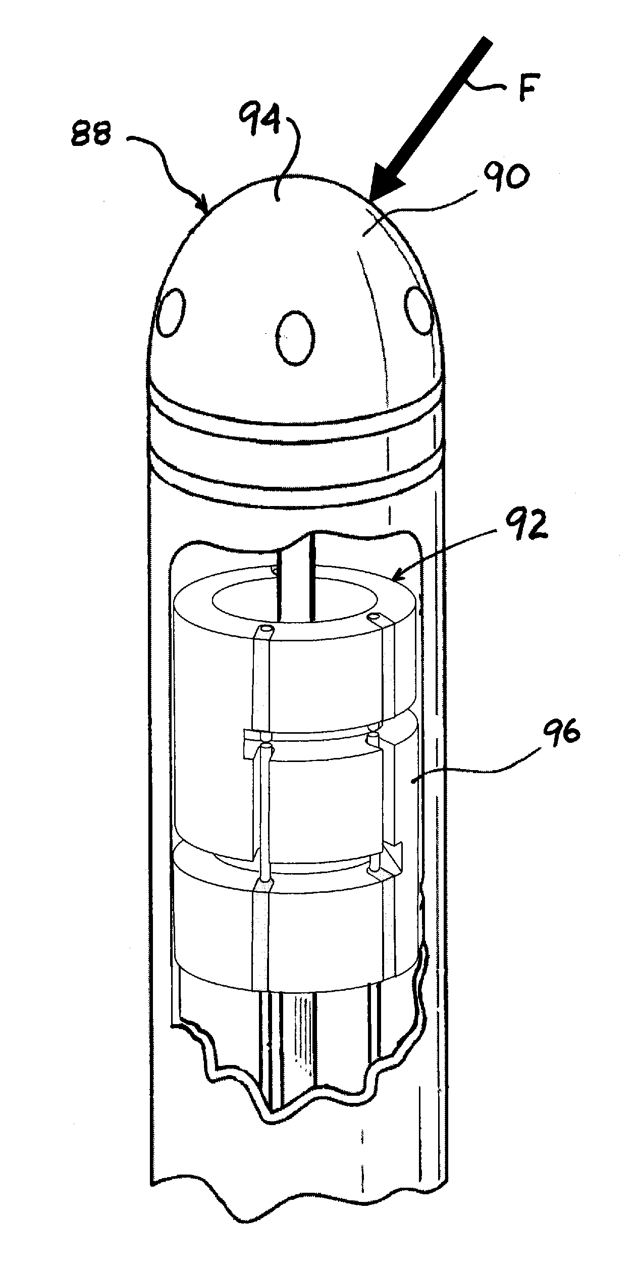
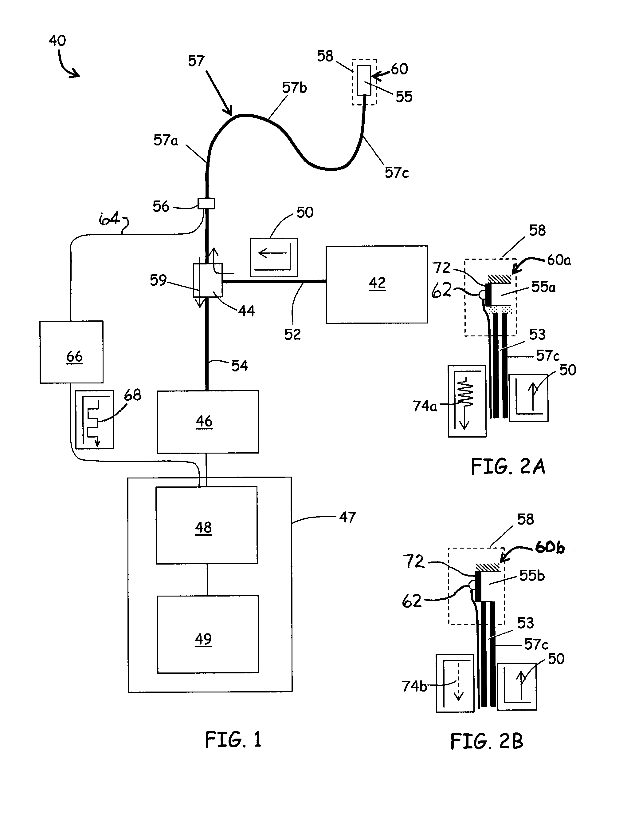
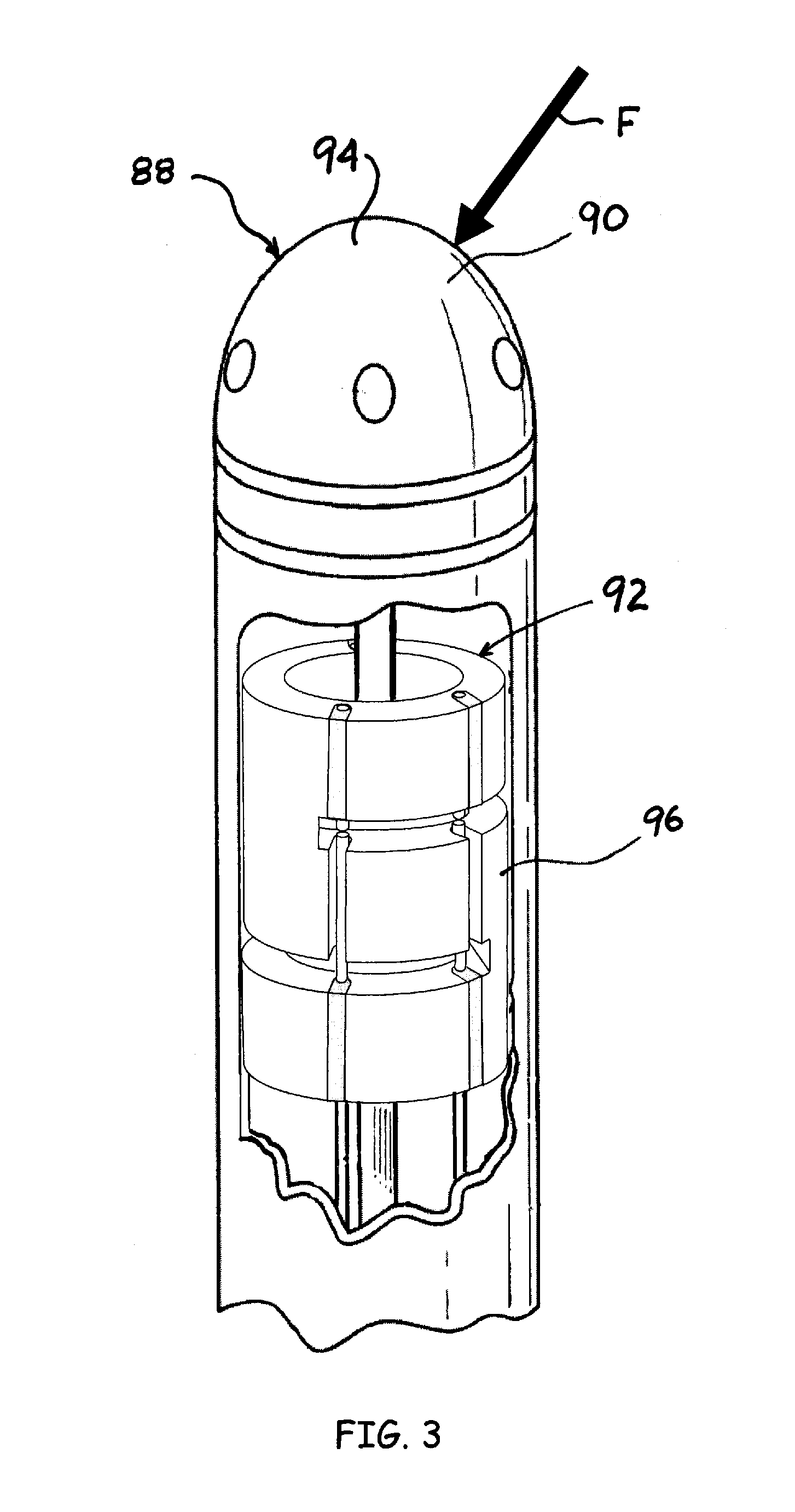
[0054]Referring to FIG. 1, an embodiment of a displacement sensing system 40 is depicted in accordance with the invention. The displacement sensing system 40 can comprise an electromagnetic source 42, a coupler 44, a receiver 46, an operator console 47 operatively coupled with a microprocessor 48 and a computer-readable storage device 49. The electromagnetic source 42 outputs a transmitted radiation 50 of electromagnetic radiation that is substantially steady state in nature, such as a laser or a broadband light source. A transmission line 52 such as a fiber optic cable carries the transmitted radiation 50 to the coupler 44, which directs the transmitted radiation 50 through a transmitting / receiving line 54 and through a fiber optic element 53 (FIG. 2A) contained within a flexible, elongate catheter assembly 57 to a fiber optic sensing element 60. The fiber optic element 53 of the catheter assembly 57 and transmitting / receiving line 54 can be coupled through a connector 56 as depict...


PUM

PropertyMeasurementUnit
Temperatureaaaaaaaaaa
Forceaaaaaaaaaa
Flexibilityaaaaaaaaaa

Abstract

An ablation catheter system configured with a compact force sensor at a distal end for detection of contact forces exerted on an end effector. The force sensor includes fiber optics operatively coupled with reflecting members on a structural member. In one embodiment, the optical fibers and reflecting members cooperate with the deformable structure to provide a variable gap interferometer for sensing deformation of the structural member due to contact force. In another embodiment, a change in the intensity of the reflected light is detected to measure the deformation. The measured deformations are then used to compute a contact force vector. In some embodiments, the force sensor is configured to passively compensate for temperature changes that otherwise lead to erroneous force indications. In other embodiments, the system actively compensates for errant force indications caused by temperature changes by measuring certain local temperatures of the structural member.

Description

RELATED APPLICATIONS[0001]This application claims the benefit of U.S. Provisional Patent Application No. 61 / 475,384, filed on Apr. 14, 2011, the disclosure of which is hereby incorporated by reference herein in its entirety.FIELD OF THE INVENTION[0002]The disclosed invention relates generally to force sensing devices capable of resolving the magnitude and direction of a force vector. More specifically, the invention relates to a force sensing tip to aid in the positioning of catheters used in humans or animals, or for serving as feedback elements in robotic surgical systems.BACKGROUND[0003]For many years, exploration and treatment of various organs or vessels has been possible using catheter-based diagnostic and treatment systems. Such catheters are introduced through a vessel leading to the cavity of the organ to be explored or treated or alternatively can be introduced directly through an incision made in the wall of the organ. In this manner, the patient avoids the trauma and ext...

Claims


Application Information

Patent Timeline
IPC IPC(8): A61B5/103G01L1/24B23P11/00
CPCA61B5/6852A61B2562/0266A61M2025/0166Y10T29/49826A61B19/46A61B2019/464A61B2017/00084G01L1/242A61B2090/064A61B90/06A61B5/6885
Inventor LEO, GIOVANNIAEBY, NICOLASOLSTAD, STUART J.BERTHOLDS, AXELLLOSAS, PERE
Owner ST JUDE MEDICAL INT HLDG SARL
Learn More