
Heater mounting system

a mounting system and heater technology, applied in the direction of air heaters, lighting and heating apparatus, heating types, etc., can solve the problems of undetectable limitation of the available head space in the vicinity of the heater, affecting the optimal and/or desirable mounting location of the heater, etc., to achieve the effect of increasing the head space and facilitating the mounting

Active Publication Date: 2012-10-18
MODINE MFG CO
View PDF2 Cites 1 Cited by
  • Summary
  • Abstract
  • Description
  • Claims
  • Application Information

AI Technical Summary

Benefits of technology

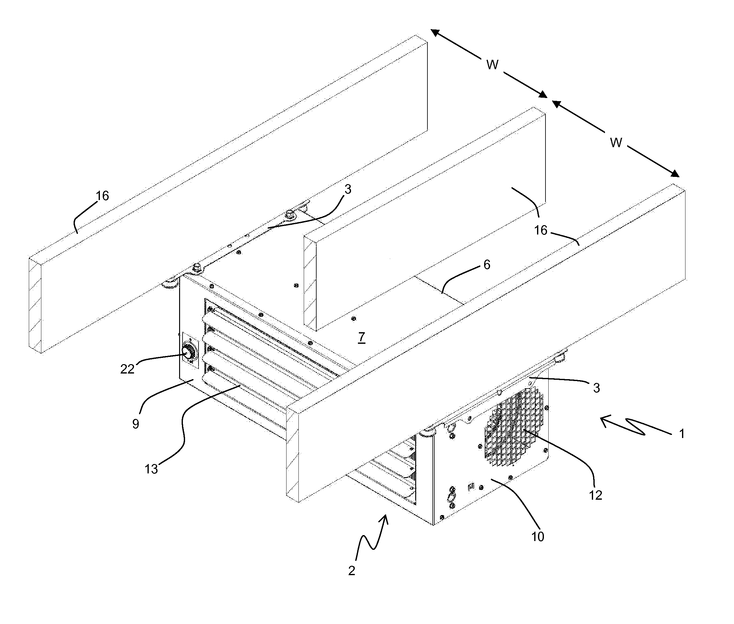
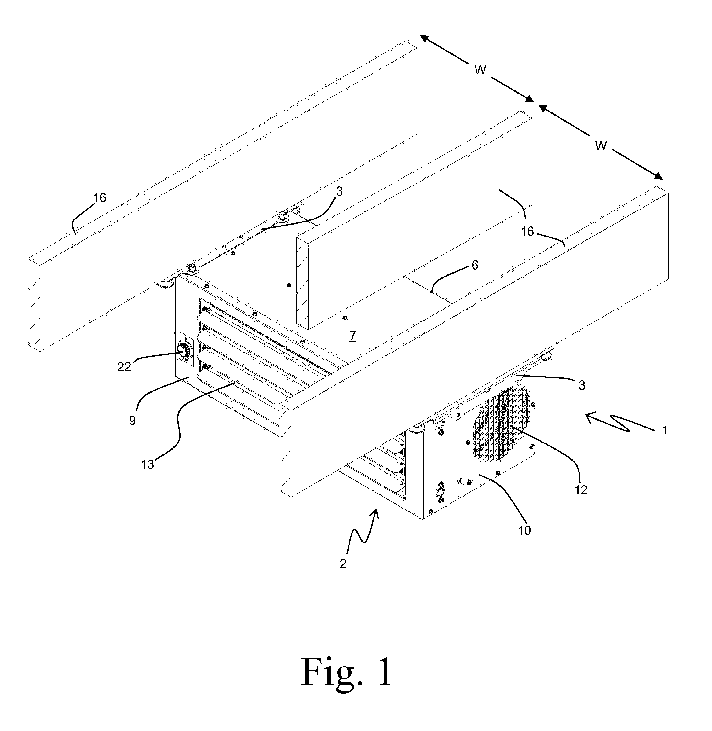
[0004]A mounting system for mounting a heater to structural members provides increased head room and flexibility of mounting. The mounting system provides mounting locations that can be located directly beneath structural members having a regular spacing, with at least two different mounting orientations. Removable brackets allow for the heater to be mounted entirely below the structural members, or with a first portion of the heater located between the structural members and a second portion located below the structural members. An air inlet can be provided in the first portion, and an air outlet can be provided in the second portion.

Problems solved by technology

This can be problematic for several reasons.
As one example of such reasons, the arrangement of the structural members of the ceiling may preclude an optimal and / or desirable mounting location, orientation, or both.
As another example, the mounting may require substantial spacing between the heater and the ceiling, thereby undesirably limiting the available head-room in the vicinity of the heater.

Method used


Image

  • Heater mounting system
  • Heater mounting system
  • Heater mounting system

Examples


Embodiment Construction

[0018]Before any embodiments of the invention are explained in detail, it is to be understood that the invention is not limited in its application to the details of construction and the arrangement of components set forth in the following description or illustrated in the following drawings. The invention is capable of other embodiments and of being practiced or of being carried out in various ways. Also, it is to be understood that the phraseology and terminology used herein is for the purpose of description and should not be regarded as limiting. The use of “including,”“comprising,” or “having” and variations thereof herein is meant to encompass the items listed thereafter and equivalents thereof as well as additional items. Unless specified or limited otherwise, the terms “mounted,”“connected,”“supported,” and “coupled” and variations thereof are used broadly and encompass both direct and indirect mountings, connections, supports, and couplings. Further, “connected” and “coupled”...


PUM


Abstract

A system for mounting a heater to structural members having a predetermined spacing includes a first mounting bracket having first and second mounting locations. The first and second mounting locations are spaced apart by a first integer multiple of the predetermined spacing. The system also includes a second mounting bracket having third and fourth mounting locations. The third and fourth mounting locations re spaced apart by the first integer multiple of the predetermined spacing. The system further includes a plurality of attachment points on the heater for attaching the first and second mounting brackets to the heater. The plurality of attachment points is arranged to locate the first, second, third, and fourth mounting locations in a mounting plane, with both the first and the third mounting locations and the second and the fourth mounting locations being spaced apart by a second integer multiple of the predetermined spacing.

Description

CROSS-REFERENCE TO RELATED APPLICATIONS[0001]This application claims priority to U.S. Provisional Patent Application No. 61 / 476,636, filed Apr. 18, 2011, the entire contents of which are hereby incorporated by reference.BACKGROUND[0002]Self-contained unit heaters to provide comfort heating of enclosed spaces are well known. Such heaters typically operate by circulating a portion of the air contained within the enclosed space through the heater, and adding heat energy to the air as it passes through the heater enclosure. The heat energy can be obtained by a variety of commonly known methods, including direct-fired, indirect-fired, hydronic, and electric resistance.[0003]In order to efficiently heat the space, as well as to provide minimal obstruction, it is common practice to mount heaters of this type to a ceiling of the enclosed space. Due to the inherent weight of such heaters, the heaters are typically secured to structural members of the ceiling. This can be problematic for seve...

Claims


Application Information

Patent Timeline
Patent Type & Authority Applications(United States)
IPC IPC(8): F24J3/00
CPCF24H3/00F24H9/06F24D5/00Y02B30/00
Inventor PERSSON, ROBERT E.
Owner MODINE MFG CO
Learn More