Sliding bearing structure for a shaft member

a technology of sliding bearing and shaft member, which is applied in the direction of bearings, shaft and bearings, rotary bearings, etc., can solve the problems of affecting the lubricating oil supply between the sliding surfaces of the shaft member and the bearing member that leaks out from both ends of the bearing member, and the temperature of the bearing portion to rise early, so as to reduce the sliding resistance, reduce the friction, and facilitate the assembly

Inactive Publication Date: 2012-10-18
TOYOTA JIDOSHA KK +1
View PDF12 Cites 7 Cited by
  • Summary
  • Abstract
  • Description
  • Claims
  • Application Information

AI Technical Summary

Benefits of technology

[0012]The invention thus provides a sliding bearing structure for a shaft member that is capable of reducing sliding resistance at low temperatures early on and will not impede cooling performance by lubricating oil at high temperatures.
[0015]According to this aspect, each annular seal member is formed by a plurality of parts, so it is easy to assemble to the shaft member or the bearing member. Also, the annular seal members deform such that at least a portion of the inside diameter of the seal members become smaller than the inside diameter of the bearing member at a low temperature, and become the same as or larger than the inside diameter of the bearing member at a high temperature. Therefore, at a low temperature, the distance between the annular seal members and the shaft member becomes less than the distance between the shaft member and the bearing member, such that the amount of lubricating oil supplied between the sliding surfaces of the shaft member and the bearing member that leaks out from both ends of the bearing member is limited. As a result, the lubricating oil retained in the bearing portion is sheared and thus heats up, causing the temperature of the bearing portion to rise early on. On the other hand, at a high temperature, the distance between the seal members and the shaft member becomes the same as or greater than the distance between the shaft member and the bearing member, so the amount of lubricating oil that leaks out from both ends of the bearing portion is not limited. As a result, good cooling action of the bearing portion by the lubricating oil is able to be displayed.
[0016]According to the aspects described above, a sliding bearing structure for a shaft member that is capable of reducing sliding resistance at low temperatures early on and will not impede cooling performance by lubricating oil at high temperatures is able to be provided.

Problems solved by technology

Therefore, at a low temperature, the distance between the annular seal members and the shaft member becomes less than the distance between the shaft member and the bearing member, such that the amount of lubricating oil supplied between the sliding surfaces of the shaft member and the bearing member that leaks out from both ends of the bearing member is limited.
As a result, the lubricating oil retained in the bearing portion is sheared and thus heats up, causing the temperature of the bearing portion to rise early on.

Method used


Image

  • Sliding bearing structure for a shaft member
  • Sliding bearing structure for a shaft member
  • Sliding bearing structure for a shaft member

Examples


Embodiment Construction

[0032]Hereinafter, example embodiments of the invention will be described in detail with reference to the accompanying drawings.

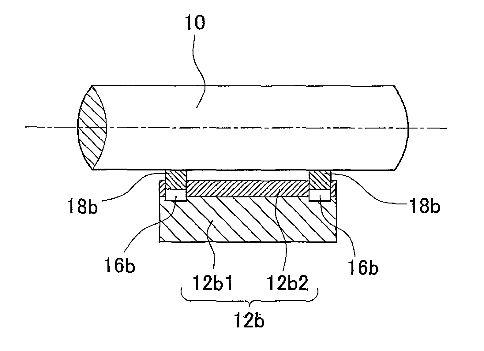
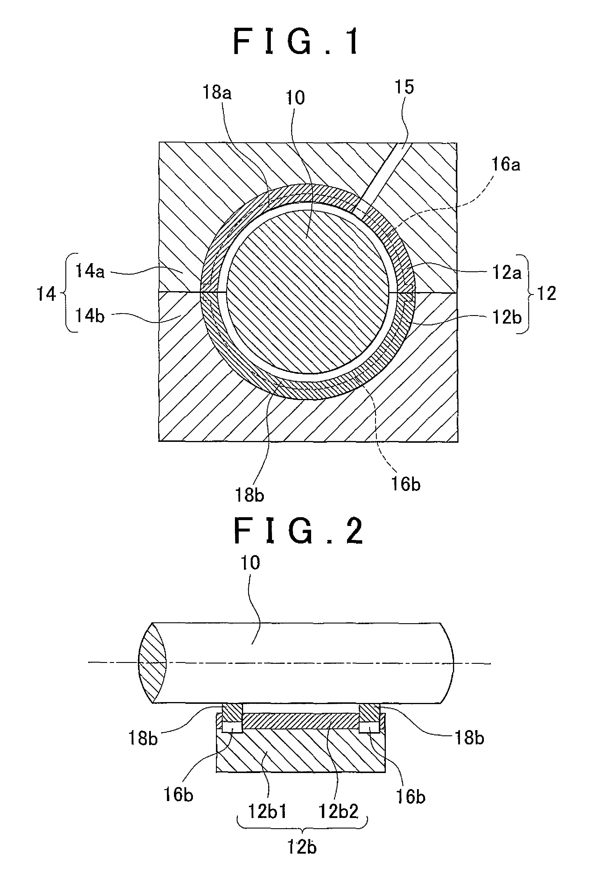
[0033]First, an example embodiment in which the invention has been applied to a sliding bearing structure of a crankshaft of an engine will be described with reference to FIGS. 1 and 2. FIGS. 1 and 2 show a main journal 10 of a crankshaft that serves as a shaft member that rotates, and a journal bearing 12 that serves as a bearing member for rotatably supporting the main journal 10. The journal bearing 12 is housed fixed, retained in a bearing housing 14 formed by an upper housing 14a that is formed in a cylinder block, not shown, and a lower housing 14b that is formed in a bearing cap that is fastened to the upper housing 14a.

[0034]The journal bearing 12 is formed by an upper journal bearing 12a and a lower journal bearing 12b. The upper journal bearing 12a is formed with an upper lining attached to an upper back plate, and the lower journal bearing 12b i...


PUM


Abstract

A sliding bearing structure for a shaft member includes: a shaft member; a bearing member rotates relative to the shaft member; an oil supply space to which lubrication is supplied between sliding surfaces of the shaft member and the bearing member; two annular grooves formed in a circumferential direction in an inner peripheral surface of the bearing member; and two annular seal members formed as separate pieces from the shaft member and the bearing member, and arranged in the annular grooves between the shaft member and the bearing member. Each annular seal member is formed in plural, and is made of material having a thermal expansion coefficient such that an inside diameter of the annular seal member is smaller than an inside diameter of the bearing member at a low temperature, and is the same as or larger than the inside diameter of the bearing member at a high temperature.

Description

INCORPORATION BY REFERENCE[0001]The disclosure of Japanese Patent Application No. 2011-090111 filed on Apr. 14, 2011 including the specification, drawings and abstract is incorporated herein by reference in its entirety.BACKGROUND OF THE INVENTION[0002]1. Field of the Invention[0003]The invention relates to sliding bearing structure for a shaft member, and more particularly, to a sliding bearing structure for a shaft member, that is used in a vehicular internal combustion engine or the like.[0004]2. Description of Related Art[0005]With a typical sliding bearing structure for a shaft member, lubricating oil is supplied to form a lubricant film in a clearance between a sliding surface of a shaft member and a sliding surface of a bearing member. Supporting a load by the oil film pressure that is created in this lubricant film reduces friction loss and helps to prevent wear and seizure.[0006]In order to keep lubricating oil in the clearance between such sliding surfaces, a bearing struc...

Claims


Application Information

Patent Timeline
Patent Type & Authority Applications(United States)
IPC IPC(8): F16C17/00F16C33/74
CPCF16C17/022F16C33/667F16C2202/22F16C37/002F16C33/74
Inventor KIMURA, YUICHIROKATO, SHINICHIHIKITA, YASUHIRO
Owner TOYOTA JIDOSHA KK
Why Eureka
Try Eureka