
Corrosive environment sensor and method for measuring corrosive environment

Inactive Publication Date: 2012-10-18
SUZUKI MOTOR CO LTD
View PDF3 Cites 0 Cited by
  • Summary
  • Abstract
  • Description
  • Claims
  • Application Information

AI Technical Summary

Benefits of technology

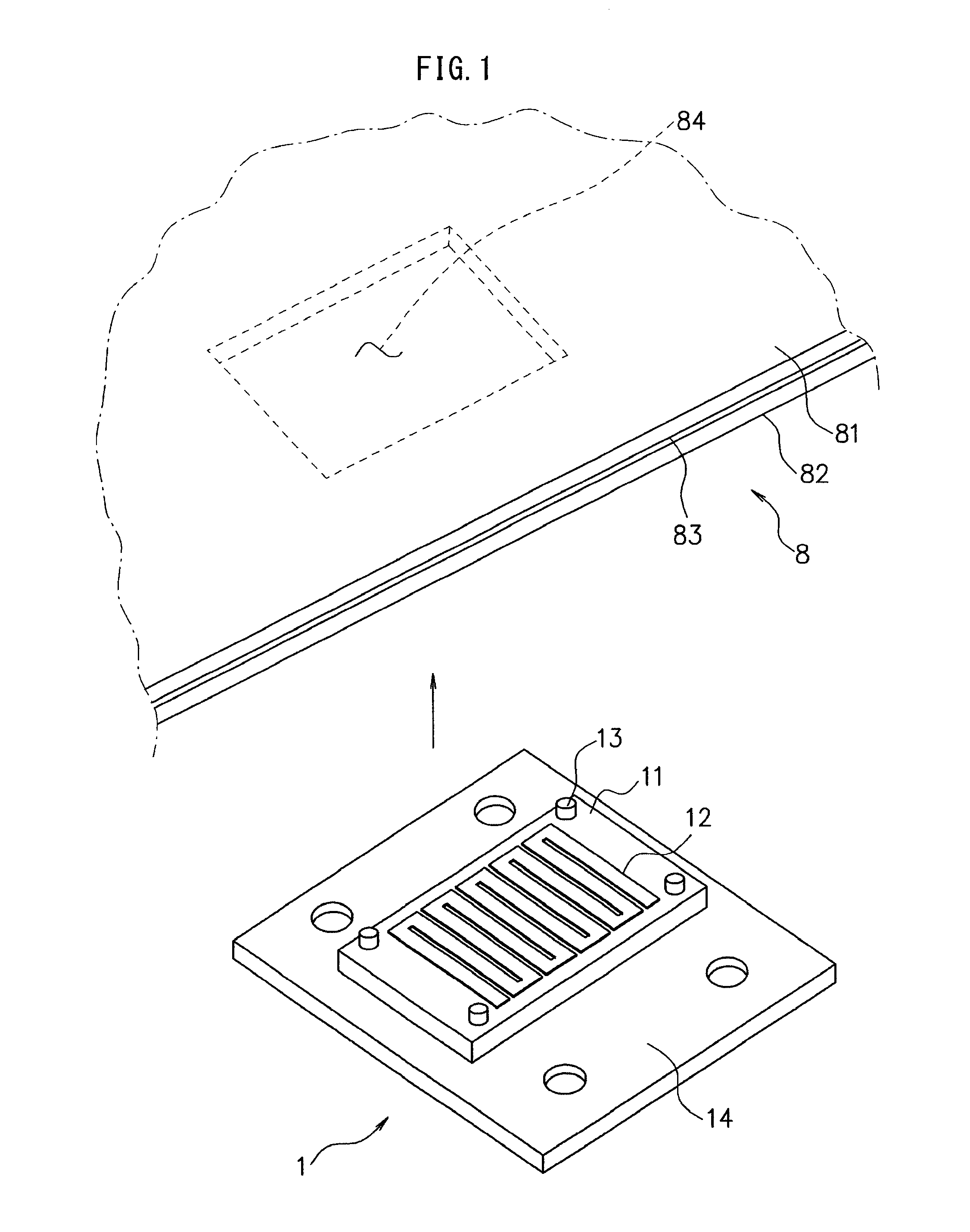
[0013]In view of the above situation, an object of the present invention is to provide a corrosive environment sensor and a method for measuring corrosive environment, which allow accurate measurement of the corrosive environment of a space generated in a portion where members overlap each other. More particularly, an object of the present invention is to provide a corrosive environment sensor and a method for measuring corrosive environment, which allow direct measurement of the corrosive environment of a space generated in a portion where members overlap each other.
[0024]According to the present invention, it becomes possible to accurately measure the corrosive environment of a space generated in a portion where members overlap each other. According to the present invention, it becomes possible to directly measure the corrosive environment of a space generated in a portion where members overlap each other in particular.

Problems solved by technology

However, since the anticorrosion paint is hard to sink into the inside of such a space, it may be impossible to sufficiently apply the anticorrosion paint to the inside of the space.
When the automobile is driven in the rain and the snow, rainwater and moisture containing snow melting agents may adhere to the structure and enter into a space therein to cause corrosion.
However, it is difficult to measure the corrosive environment inside a space present in the structure with use of the ACM sensor.
When the electrodes of the ACM sensor come into contact with the structure, electric current may pass between the electrodes and the structure and also the electrodes may short-circuit to each other, which may hinder accurate measurement of the galvanic current.
Since the size of the spaces present in the structure is generally small, it is difficult to place the ACM sensor inside minimal spaces without the electrodes coming into contact with the structure.
However, it is difficult to fully reproduce the environment.
Moreover, the measurement results have large individual differences and variations.
However, the corrosive environment sensor disclosed in Patent Document 1 cannot be placed directly in the space of the portion where the members overlap each other.
It is not possible, therefore, to make the corrosive environment of a pseudo space formed in the corrosive environment sensor completely coincident with the actual corrosive environment of the portion where members overlap each other.

Method used


Image

  • Corrosive environment sensor and method for measuring corrosive environment
  • Corrosive environment sensor and method for measuring corrosive environment
  • Corrosive environment sensor and method for measuring corrosive environment

Examples


working example

[0040]A description is now given of a measurement example (working example) of the corrosive environment with use of the corrosive environment sensor 1 of the present invention in comparison to measurement examples (comparative examples 1 and 2) of the corrosive environment with use of conventional corrosive environment sensors 91 and 92 with reference to FIG. 4 and FIG. 5. The corrosive environment sensor 1 and the conventional corrosive environment sensors 91 and 92 were attached to a front member 6 of an automobile, and the automobile was driven in the rain to measure a galvanic current. FIG. 4 is a cross sectional view for schematically showing the mounting configuration of the corrosive environment sensor 1 and the conventional corrosive environment sensors 91 and 92 to the front member 6. FIG. 5 is a graph view showing measurement results of galvanic current with use of the corrosive environment sensor 1 and the conventional corrosive environment sensors 91 and 92. One convent...


PUM


Abstract

A corrosive environment sensor for measuring corrosive environment inside a space between a first member that is a conductor and a second member that is a conductor or insulator includes: a base having a surface which cam face the first member that is a conductor; and an electrode which is provided on the surface of the base and formed with a material different in ionization tendency from the first member and which faces at a distance the first member so as to form a galvanic coupling with the first member, and the corrosive environment sensor measures a galvanic current between the electrode and the first member.

Description

CROSS-REFERENCE TO RELATED APPLICATIONS[0001]This application is based upon and claims the benefit of priority of the prior Japanese Patent Application No. 2011-089507, filed on Apr. 13, 2011, the entire contents of which are incorporated herein by reference.BACKGROUND OF THE INVENTION[0002]1. Field of the Invention[0003]The present invention relates to corrosive environment sensors and methods for measuring corrosive environment. More specifically, the present invention relates to a corrosive environment sensor preferable for measuring the corrosive environment inside a space present in a structure and a method for measuring corrosive environment inside a space present in a structure with use of the corrosive environment sensor. The term “corrosive environment” herein refers to an influence of environment exerted on the corrosion of a structure and the like (i.e., corrosiveness of the environment).[0004]2. Description of the Related Art[0005]A structure constituted by combining met...

Claims


Application Information

Patent Timeline
IPC IPC(8): G01N17/02
CPCG01N17/043
Inventor NAKADA, RURIKONAGAI, NOBUTOSHISAKO, KOTAITO, YUYA
Owner SUZUKI MOTOR CO LTD
Learn More