Hardfaced Wearpart Using Brazing And Associated Method And Assembly For Manufacturing

Active Publication Date: 2012-10-11
ESCO GRP LLC
View PDF4 Cites 15 Cited by
  • Summary
  • Abstract
  • Description
  • Claims
  • Application Information

AI Technical Summary

Benefits of technology

[0025]Other aspects of the invention relate to a method for producing a composite wear-resistant tool that includes the step of infiltrating a layer of hard particles confined between a substrate and an expendable sheet-metal shell. The shell may be constructed such that it confines the hard particles to desired locations on the substrate, with specific thicknesses and shapes defined by contours of both the substrate and the shell. The shell may also be constructed such that it defines a reservoir for containing infiltrating material which will be melted during the step of infiltrating. Almost any type of tool or component that is hardfaced now by welding could be hardfaced by the disclosed methods. These methods may include a step where the particulate material is selected with a type and size distribution so as to give the desired degree of wear resistance for the intended application. These methods may include a step where the particulate material and its size distribution, as well as the type of infiltrating material employed are selected so as to give a desired degree of wear resistance for an intended application, while at the same time accommodating the thermal and transformation expansion differences between the infiltrated layer and the substrate so as to minimize or eliminate cracking and spelling.

Problems solved by technology

The thin metal shell is expendable, because it typically erodes quickly during use of these hardfaced wearparts.

Method used


Image

  • Hardfaced Wearpart Using Brazing And Associated Method And Assembly For Manufacturing
  • Hardfaced Wearpart Using Brazing And Associated Method And Assembly For Manufacturing
  • Hardfaced Wearpart Using Brazing And Associated Method And Assembly For Manufacturing

Examples


Embodiment Construction

[0075]While this invention is susceptible of embodiment in many different forms, there are shown in the drawings, and will herein be described in detail, preferred embodiments of the invention with the understanding that the present disclosure is to be considered as an exemplification of the principles of the invention and is not intended to limit the broad aspects of the invention to the embodiments illustrated and described.

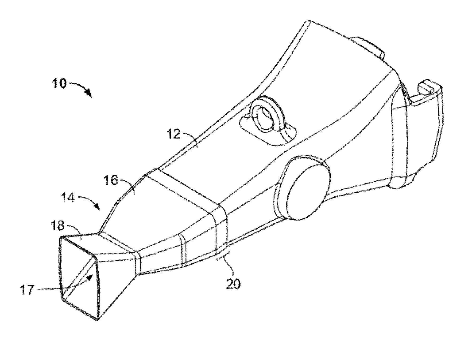
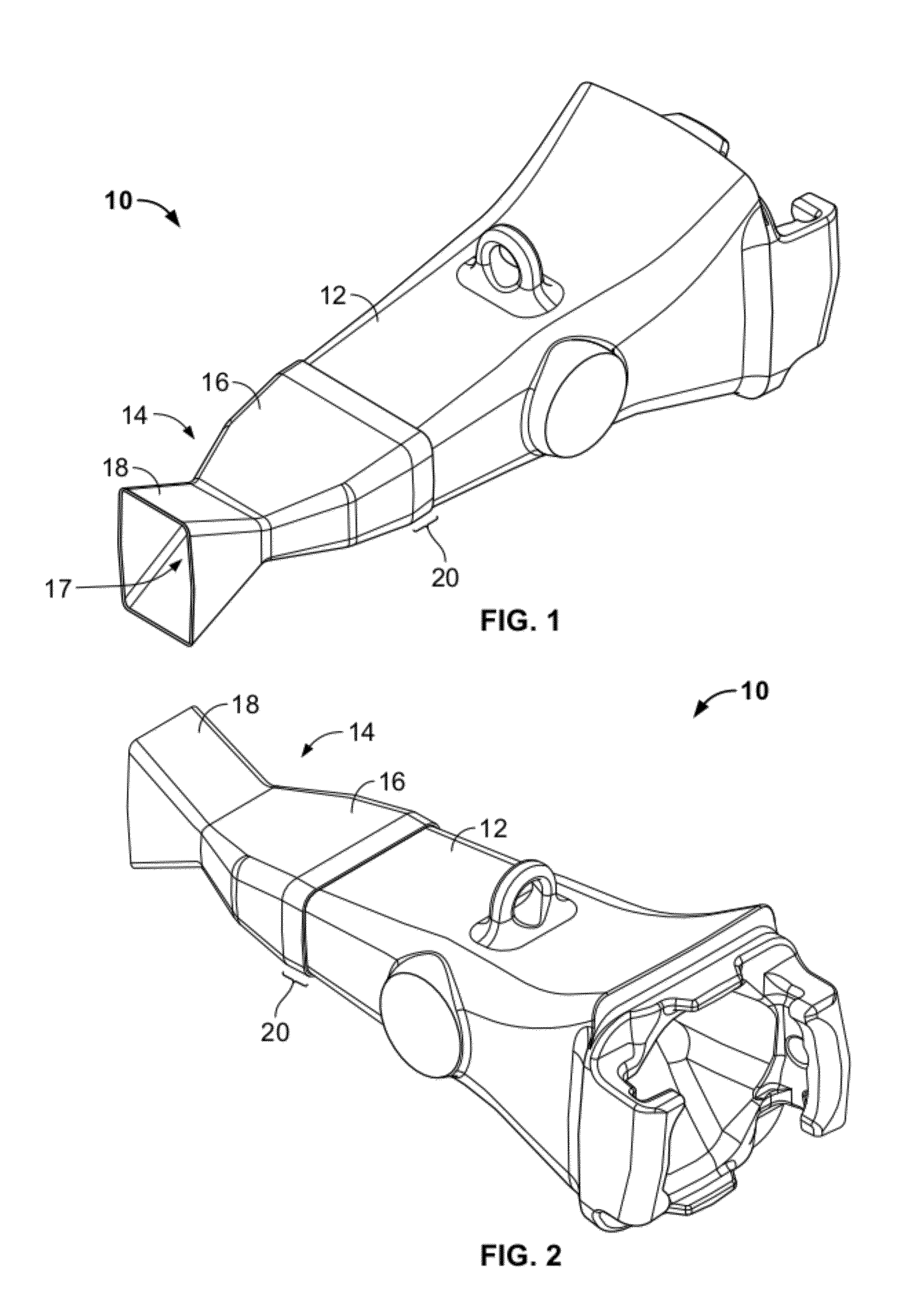
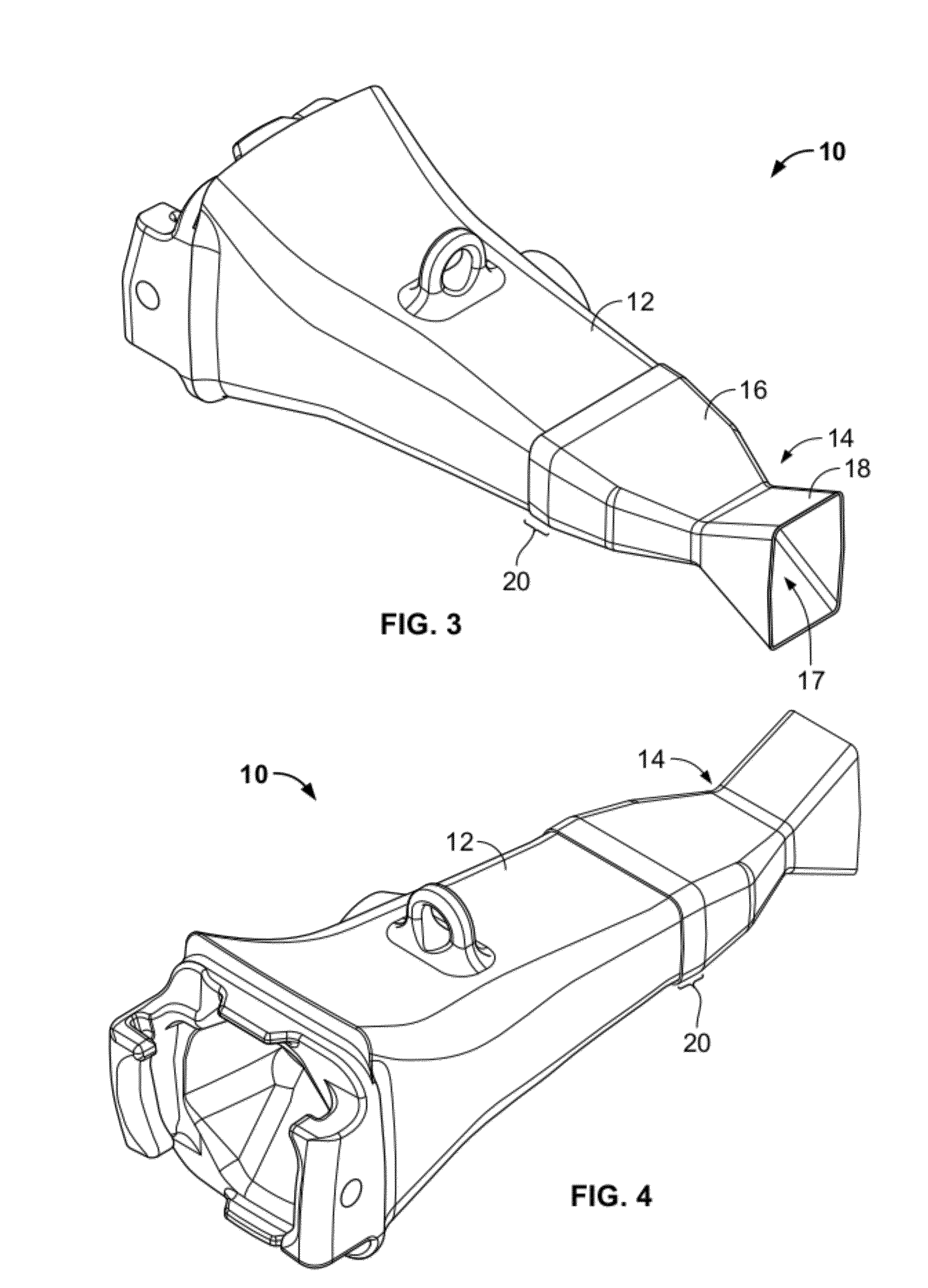
[0076]In general, the disclosure relates to the use of a metal shell in forming a composite material or other wear resistant material on the surface of a substrate, such as a wearpart, using brazing and / or infiltration techniques, as well as articles formed using such techniques and methods and equipment incorporating such techniques. For example, an article (e.g. a hardfaced wearpart) formed using such techniques may include a substrate, a sheet metal shell connected to the substrate to define a cavity between the surface of the substrate and the shell, and a ...


PUM

PropertyMeasurementUnit
Temperatureaaaaaaaaaa
Wear resistanceaaaaaaaaaa

Abstract

An article, such as a hardfaced wearpart, includes a substrate, a sheet metal shell connected to the substrate to define a cavity between the surface of the substrate and the shell, and a composite material filling the cavity and forming a coating on at least a portion of the surface of the substrate, the composite material including a hard particulate material infiltrated with a metallic brazing material. The shell may be connected to the substrate by welding or brazing to the substrate, and may wear away during use. The shell and the substrate may be used as part of an assembly for producing the article, where the shell is used as a mold for forming the composite material by filling the shell with the hard particulate material and subsequently infiltrating with the brazing material.

Description

CROSS-REFERENCE TO RELATED APPLICATION[0001]The present application claims priority to U.S. Provisional Application No. 61 / 472,470, filed Apr. 6, 2011, which application is incorporated by reference herein in its entirety and made part hereof.TECHNICAL FIELD OF THE DISCLOSURE[0002]This disclosure relates to various embodiments of a hardfaced part for use in abrasive environments formed using infiltration brazing or another brazing technique. More particularly, the disclosure relates to products, systems and methods that pertain to such hardfaced parts. For example, such hardfaced parts can include wear-resistant tools used for ground-engaging machinery (e.g., a point for an excavator), mineral processing equipment such as a tip for a dual roll crusher, trommel screens, or other abrasive applications.BACKGROUND[0003]Examples of wear parts produced by infiltration of hard particles are disclosed in U.S. Pat. Nos. 4,884,477, 4,949,598, and 6,073,518, and in the publications US201002786...

Claims


Application Information

Patent Timeline
IPC IPC(8): B32B3/02B23K31/02B32B3/00
CPCB23K1/00B23K1/0008B23K31/02Y10T428/24917B23K2203/04B23K35/365Y10T428/23B23K2201/20B32B15/043B23K2101/20B23K2103/04B23K31/025B23K1/20C23C24/103B22D19/08B22D23/06E21C35/183B32B15/04B05D3/02B05D5/00E02F9/285
Inventor CHURCHILL, ROBIN KERRY
Owner ESCO GRP LLC
Why Eureka
Try Eureka