
Adjustable multiple-piece cam track

Active Publication Date: 2012-10-04
GRAHAM ENG CO LLC
View PDF3 Cites 26 Cited by
  • Summary
  • Abstract
  • Description
  • Claims
  • Application Information

AI Technical Summary

Problems solved by technology

However, due to the relatively large size of the cam tracks (generally 50-60 inch radius), these cam tracks are difficult and costly to manufacture and ship.
In addition, when adjustments or maintenance is required on the cam tracks, the blow molding apparatus must generally be taken out of operation for a significant period of time while the adjustments or maintenance are performed.

Method used


Image

  • Adjustable multiple-piece cam track
  • Adjustable multiple-piece cam track
  • Adjustable multiple-piece cam track

Examples


Embodiment Construction

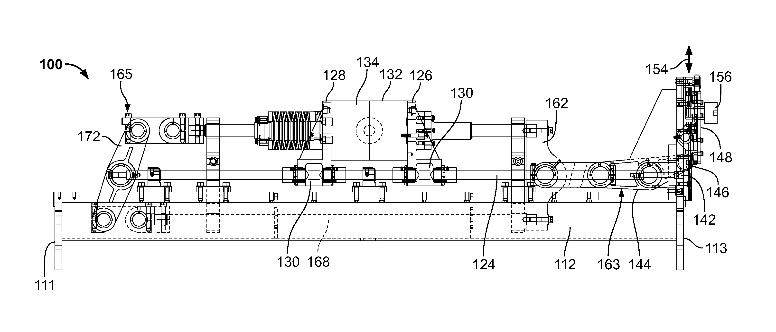
[0021]The exemplary adjustable multiple-piece cam track described herein can be used with various rotary type machines, including, but not limited to, the exemplary rotary blow molding machine shown and described in co-pending U.S. patent application Ser. No. 12 / 898,832, filed on Oct. 6, 2010, which is hereby incorporated, in its entirety, by reference.

[0022]The exemplary rotary blow molding machine is adapted to engage a tubular parison and transform the same into hollow, molded objects, such as containers of various types. As is known in the industry, the parison comprises resin which is homogeneously melted within an extruder of suitable type.

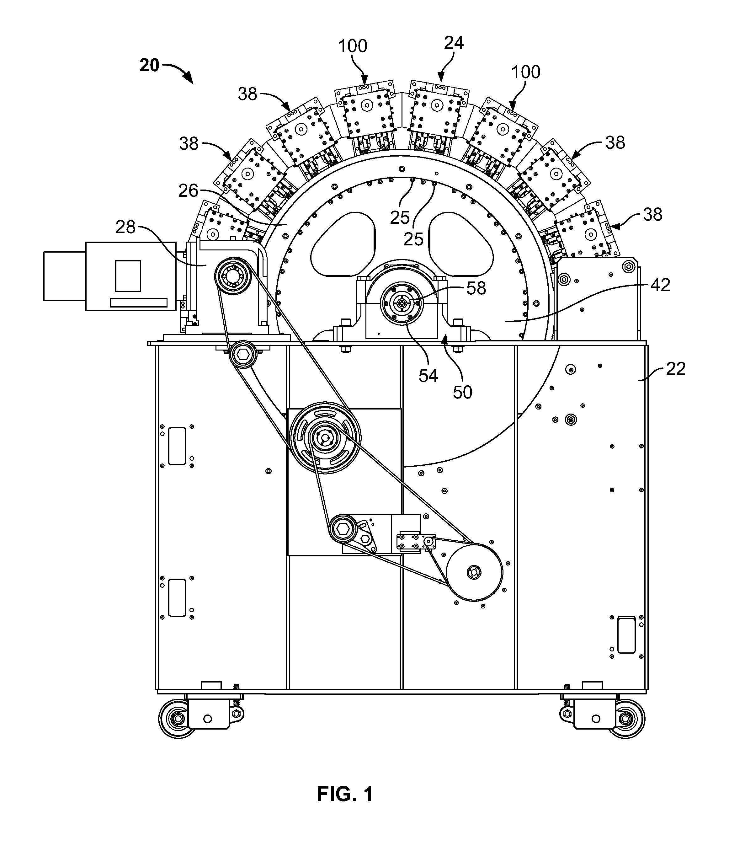
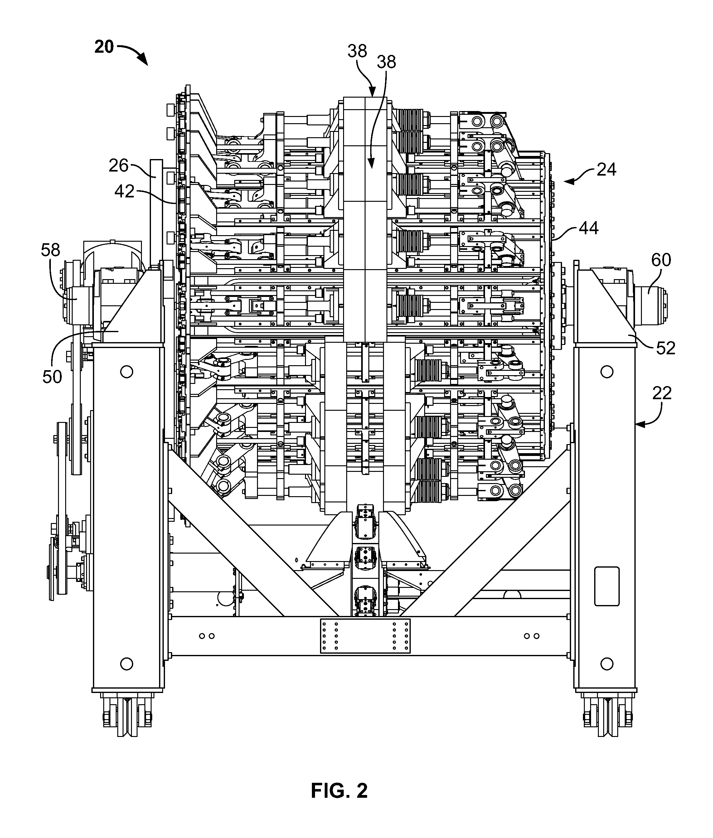
[0023]Referring now to FIG. 1 and FIG. 2, the exemplary plastic blow molding machine 20 includes a base 22 and a movable member or wheel 24 mounted on the base for rotation thereon about a rotational axis A. The movable member 24 may be in the form of a wheel or other such configurations which are rotatable about the rotational axis. As illu...


PUM

PropertyMeasurementUnit
Diameteraaaaaaaaaa

Abstract

A multiple-piece cam unit for use in a molding machine. The cam unit has a cam track which engages cam followers of mold assemblies of the molding machine to move the cam followers between a first position and a second position. The cam unit includes a first cam section and a second cam section. The first cam section has an entrance portion which is dimensioned to receive the cam followers therein. The second cam section has an exit portion positioned to release the cam followers therefrom. The second cam section is moveably mounted to the molding machine to allow the exit portion of the second cam section to be moved relative to the entrance portion of the first cam section, to insure that the cam followers exiting the exit portion of the second cam section are properly aligned to enter the entrance portion of the first cam section.

Description

FIELD OF THE INVENTION[0001]The invention relates generally to a rotary molding apparatus. Specifically, the present invention relates to an adjustable cam track for use with the rotary molding apparatus.BACKGROUND OF THE INVENTION[0002]Conventional rotary extrusion blow molding apparatuses typically have a structural frame mounted on a rotating shaft. The structural frame has a plurality of molds mounted thereon and is known in the industry as a wheel. As the wheel is rotated, the plurality of molds is rotated past an extrusion die extruding a continuous parison. Each mold typically includes two mold halves, each comprising a mold cavity half therein, such that when the mold halves are closed, the mold defines a mold cavity corresponding to the configuration of the article to be molded, such as a container. Each mold, seriatim, is rotated past the extrusion die with the mold halves in an open configuration. The mold halves of each mold are then closed around the parison to enclose ...

Claims


Application Information

Patent Timeline
IPC IPC(8): B29C33/22F16H53/04
CPCB29C49/4236B29C49/56B29C49/36Y10T74/2102B29C33/36B29C33/22B29C49/04B29C49/5602B29C49/5603
Inventor MATHY, JR., JOHN M.KLINEDINST, SR., PAUL W.
Owner GRAHAM ENG CO LLC
Learn More