
Method and apparatus for mapping traffic using virtual concatenation

a technology of virtual concatenation and traffic, applied in the direction of electrical apparatus, multiplex communication, transmission, etc., can solve the problems of lag in the traffic distribution mechanism, long time for all data to be transmitted, and rules that do not know the actual bandwidth requirements of packet flows

Active Publication Date: 2012-10-04
INFINERA CORP
View PDF3 Cites 33 Cited by
  • Summary
  • Abstract
  • Description
  • Claims
  • Application Information

AI Technical Summary

Benefits of technology

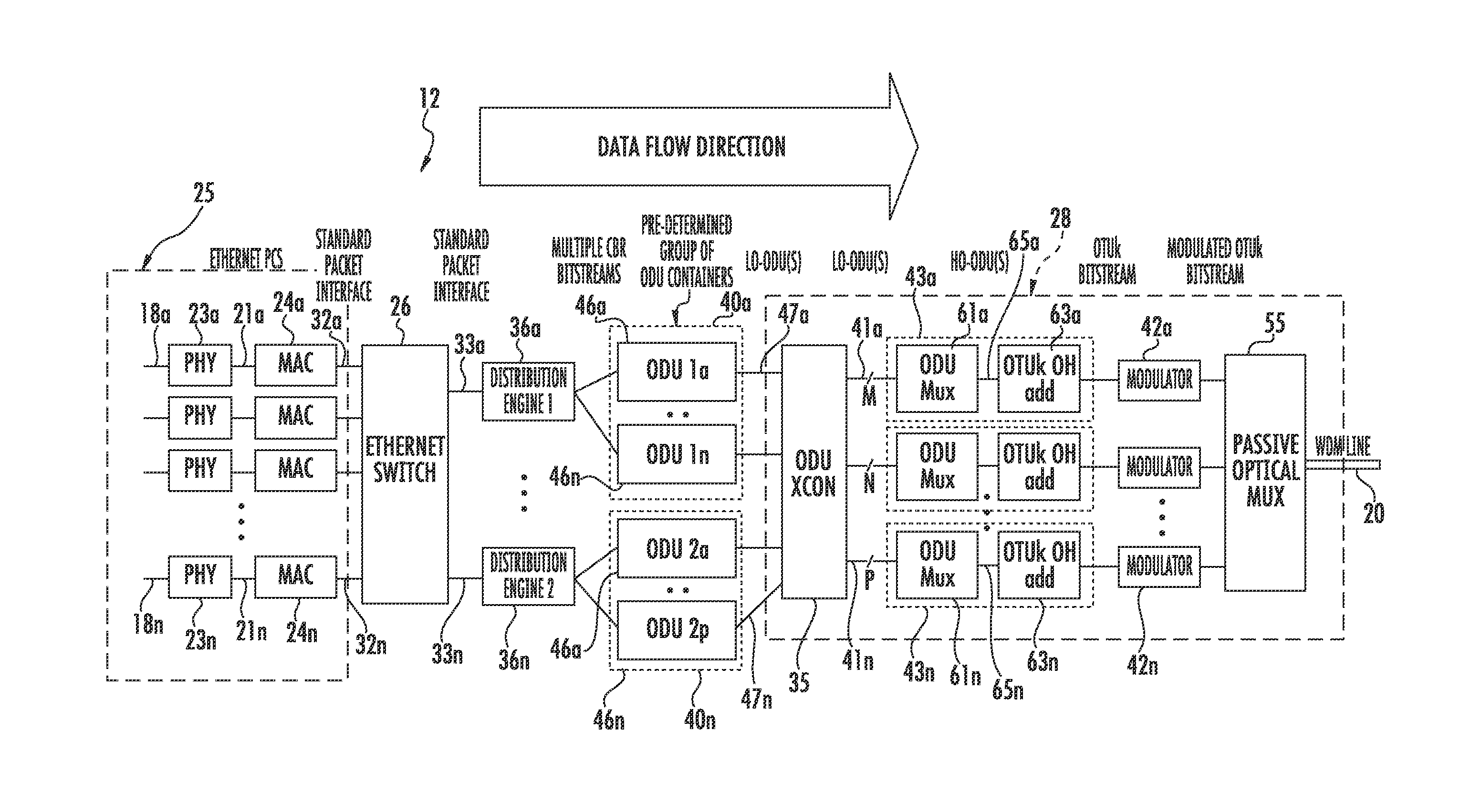
The present disclosure is about a node that can receive and process packets of data. The node has a packet network interface, an ethernet switch, an optical port, and a distribution engine. The distribution engine can read virtual queues of data and provide them to different circuits for transmission. The virtual queues can include bits of data that need to be processed. The distribution engine also adds markers to the data to help with the processing of the data at the destination node. The technical effect of this disclosure is to improve the efficiency and accuracy of processing packets of data in a network.

Problems solved by technology

This circuit typically has a fixed bandwidth which poses some disadvantages where the amount of data is large relative to the link's bandwidth, as it may take a long time for all of the data to be transmitted.
However, a major disadvantage is that the traffic distribution mechanism of LAG is based on static classification rules (based on combination of fields contained in data packets).
Such rules have no knowledge of the actual bandwidth requirements of the packet flows.
As a result, the performance of a LAG implementation is sensitive to the actual data flowing through the LAG, and becomes inefficient at data rates in excess of 1 Gbit / sec.
At these data rates, link aggregation may result in uneven spread of the packets over the available communication links.
This can result in under-utilizing the available bandwidth of some of the communication links, while placing more traffic than a communication link can handle through other communication links, which results in congestion and dropped packets.
Then, the end node reassembles the packets in the correct order, which causes additional time delays.

Method used


Image

  • Method and apparatus for mapping traffic using virtual concatenation
  • Method and apparatus for mapping traffic using virtual concatenation
  • Method and apparatus for mapping traffic using virtual concatenation

Examples


Embodiment Construction

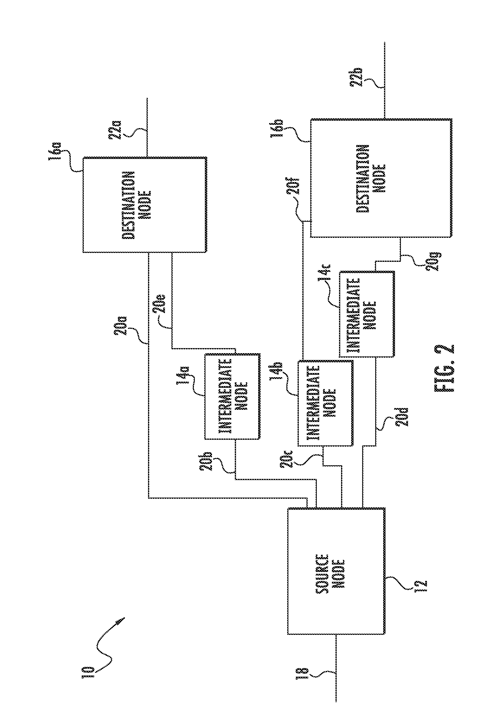
[0033]The prior art methods for transporting high-speed packet flows over optical networks using link aggregation groups fail to evenly distribute data from the packet flows over the available links, which results in failure to utilize the full available bandwidth of the links and / or overloading certain links, which in turn may result in dropped packets. The inventive concept disclosed herein overcomes such prior art deficiencies by assigning packets within the packet flows to virtual concatenation groups (VCG) based upon destination, and then evenly distributing data from the packets within the virtual concatenation groups into predetermined groups of plurality of circuits which may be referred to herein as VCG members. The inventive concept disclosed herein can utilize the full available bandwidth of the set of circuits without overloading certain circuits relative to other circuits which results in increased utilization of available bandwidth and less dropped packets. The distrib...


PUM


Abstract

A node comprising a packet network interface, an ethernet switch, an optical port, and a distribution engine. The packet network interface adapted to receive a packet having a destination address and a first bit and a second bit. The ethernet switch is adapted to receive and forward the packet into a virtual queue associated with a destination. The optical port has circuitry for transmitting to a plurality of circuits. The distribution engine has one or more processors configured to execute processor executable code to cause the distribution engine to (1) read a first bit and a second bit from the virtual queue, (2) provide the first bit and the second bit to the at least one optical port for transmission to a first predetermined group of the plurality of circuits.

Description

FIELD OF DISCLOSURE[0001]The inventive concept disclosed herein generally relates to a method and apparatus for transporting data flows over optical networks, and more particularly but not by way of limitation, to a method and apparatus for transporting high-speed packet flows over optical networks having multiple circuits with virtual concatenation techniques to evenly distribute bits from the packet flows across multiple circuits using optical channel data units.BACKGROUND[0002]Information networks are well known in the art and function to transmit information such as computer data between various computer systems operably coupled to the information network. Generally there are two types of information networks—circuit switched and packet switched. Circuit switched networks operate by creating, maintaining and transmitting data over a circuit between two network nodes. This circuit typically has a fixed bandwidth which poses some disadvantages where the amount of data is large rel...

Claims


Application Information

Patent Timeline
Patent Type & Authority Applications(United States)
IPC IPC(8): H04J14/00
CPCH04J2203/0085H04L47/34H04L47/125H04J2203/0094
Inventor VALIVETI, RADHAKRISHNAPAN, PINGTANGIRALA, RAVISPRAGUE, EDWARD E.RAO, RAJANLU, BIAO
Owner INFINERA CORP
Learn More