Power factor correction boost converter and frequency switching modulation method thereof

a power factor correction and boost converter technology, applied in the field of power factor correction, can solve the problems of increasing switching loss, negatively affecting the conversion efficiency of the overall power supply, etc., and achieve the effects of reducing switching loss, enhancing the conversion efficiency of power converters, and fixing loss of magnetic components

Active Publication Date: 2012-10-04
LITE ON TECH CORP +1
View PDF4 Cites 9 Cited by
  • Summary
  • Abstract
  • Description
  • Claims
  • Application Information

AI Technical Summary

Benefits of technology

[0007]The present disclosure provides a Power Factor Correction (PFC) boost converter adapted for a power supply with a PFC boost converter. Through a control unit, the instant boost converter may adjust the switching frequency according to the output load level thereof to reduce the switching loss, the fixed loss of magnetic components, etc, thereby enhancing the conversion efficiency of the power converter.
[0010]From another view, the present disclosure also provides a switching frequency modulation method of a PFC boost converter, wherein the PFC boost converter adjusts the power outputted to a voltage converter, the above-mentioned switching frequency modulation method includes the following steps: detecting an output load of the PFC boost converter; detecting the variation of the output load, increases the frequency of the PWM signal as the output load of the PFC boost converter increases; and reduces the frequency of the PWM signal as the output load of the PFC boost converter decreases.
[0011]In summary, the instantly disclosed PFC boost converter may be configured to modulate the switching frequency according to the output load. When the output load is small, the controller reduces the switching frequency automatically to reduce the switching loss of the PFC boost converter. Particularly under light and medium load conditions, the present disclosure may automatically operate under lower switching frequency to minimize the power loss.

Problems solved by technology

However, maintaining at a fixed switching frequency (at a high value, especially) is often undesirable when the switching power supply is only carrying light or medium loads, as it will increase switching loss, driver loss, and core loss of the power transistor, thus negatively affecting the conversion efficiency of the overall power supply.

Method used


Image

  • Power factor correction boost converter and frequency switching modulation method thereof
  • Power factor correction boost converter and frequency switching modulation method thereof
  • Power factor correction boost converter and frequency switching modulation method thereof

Examples


first embodiment

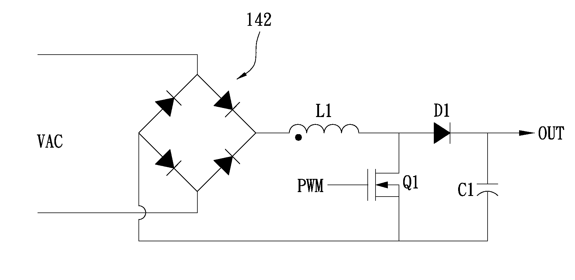
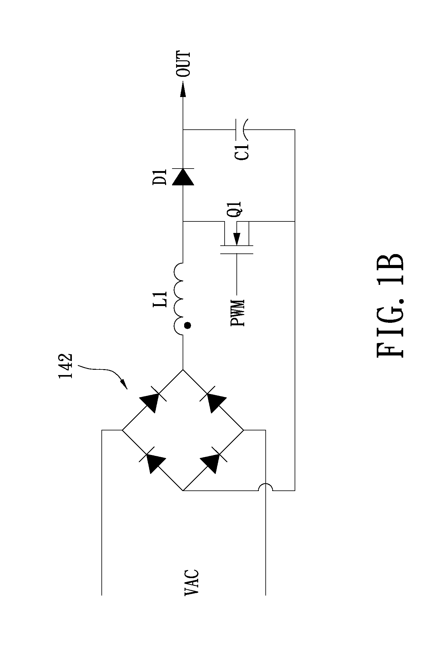
[0029]Please refer to FIG. 1A, which provides a function block diagram of a Power Factor Correction (PFC) boost converter in accordance with the first exemplary embodiment of the present disclosure. The PFC boost converter 100 can be configured to generate a power output to a back-end voltage converter 150, through which the power output into a direct current (DC) voltage is converted to power various electronic systems or components. The PFC boost converter 100 includes a control unit 101 and a PFC converter unit 140, wherein the PFC converter unit 140 for example, may be a CCM PFC converter. The control unit 101 further includes a control circuit 110, a current detection circuit 120, and a voltage detection circuit 130. The current detection circuit 120 is configured to generate a first detection signal DS1 responsive to an output load current of the PFC converter unit 140. The voltage detection circuit 130 is configured to generate a second detection signal DS2 responsive to the ...

second exemplary embodiment

[0047]Various models of the PWM signal controllers may be suitably adapted in the instantly disclosed PFC boost converter, and each model may employ different frequency modulation methods. FIG. 8 shows the main internal circuitry diagram of a control circuit 110 in accordance with the second exemplary embodiment of the present disclosure. As shown in FIG. 8, controller 830 configures the pin P3 as a frequency setting pin, and pin P1 for outputting a signal VEAO, which is responsive to the output load voltage of the Power Factor Correction (PFC) converter unit 140. The resistor RT is coupled between the pin P3 of the controller 830 and a ground GND, and the two terminals of the resistor RT are represented in T1, T2, respectively. The controller 830 may modulate the frequency of the PWM signal according to the resistance received at the pin P3. It is noteworthy, that the controller type and the associated peripheral circuitry may be set according to the specific designs and the requir...


PUM


Abstract

The instant disclosure provides a Power Factor Correction (PFC) boost converter including a PFC converter unit and a control unit and a frequency switching modulation method thereof. The control unit outputs a pulse width modulation (PWM) signal to the PFC converter unit for adjusting an electronic power output to a voltage converter. As the output load of the PFC converter unit increases, the control unit increases the frequency of the PWM signal. Conversely, as the output load of the PFC converter unit decreases, the control unit reduces the frequency of the PWM signal. Consequently, the switching loss of the PFC converter unit is reduced.

Description

BACKGROUND[0001]1. Technical Field[0002]The present disclosure relates to a Power Factor Corrector, in particular, to a Power Factor Correction (PFC) boost converter applied in high efficiency switching power supply applications.[0003]2. Description of Related Art[0004]The growing awareness in environmental protection and the global warming issues have driven energy conservation to become a major policy agenda around the world. The U.S. Environmental Protection Agency (EPA) have adopted regulations that impose higher efficiency requirements on all types of electronic equipments to achieve the objective of energy saving. For instance, the basic 80 PLUS level requirement imposed on the PC power supply (80%, 80%, 80%), as well as certifications like 80 PLUS bronze (82%, 85%, 82%), 80 PLUS silver (85%, 88%, 85%), or 80 PLUS gold (87%, 90%, 87%). Hence increasing in power switching efficiency is a major current issue which we must overcome.[0005]In the field of power electronics, the alt...

Claims


Application Information

Patent Timeline
Patent Type & Authority Applications(United States)
IPC IPC(8): G05F1/70
CPCY02B70/126H02M1/4225Y02B70/10
Inventor CHEN, CHIH-TAILIN, YU-HO
Owner LITE ON TECH CORP
Why Eureka
Try Eureka