Energy management for wireless sensor networks

a wireless sensor and energy management technology, applied in the field of remote sensor networks, can solve the problems of not necessarily returning the most useful range of information from the node during the lifetime, and achieve the effects of sufficient energy, time-consuming and expensive, and typically unpredictable energy harvesting

Inactive Publication Date: 2012-09-27
COMMONWEALTH SCI & IND RES ORG
View PDF1 Cites 15 Cited by
  • Summary
  • Abstract
  • Description
  • Claims
  • Application Information

AI Technical Summary

Benefits of technology

[0004]The main advantage is not only that the invention ensures continuing operation of the node for a specified lifetime, but also that it able to select the best behaviour for the node depending upon the state the phenomena is most likely to be in at any given time.
[0017]In this example transitions in light levels may not trigger changes from the day or night states unless corroborated by data from the UV sensor. This may, for instance, prevent an increase in sampling rate of the light sensor resulting from exposure to artificial night-time illumination. The node may also be arranged to increase the sampling rate of the UV sensor for a period of time after the data from the light sensor exhibits a change by more than a predetermined threshold. The overall effect might be that the UV sensor is sampled more frequently when events occur that could be dawn or dusk, whereas the light sensor is sampled more frequently only during the daylight hours. Many other variations are possible, for instance it may be possible to stop sampling a particular sensor when the phenomena is in a particular state.
[0024]This invention may enable true long-term deployments of sensor networks where each sensor node can be guaranteed to last a specified lifetime. This is particularly important for outdoor, environmental sensing where replacement of energy storage is time-consuming and expensive, and energy harvesting is typically unpredictable.
[0025]In a second aspect the invention may be applied over a network of sensor nodes. In a network each node periodically announces its residual energy value and the minimum energy of any neighbor node along it reporting path. In this way each node learns the minimum residual energy in its region of the network, and is able to set its sensor sampling rates in order to conserve sufficient energy at critical nodes of the network along its reporting path.

Problems solved by technology

Although such protocols may enable nodes to last for a specified lifetime, they do not necessarily return the most useful range of information from the node during that lifetime.

Method used


Image

  • Energy management for wireless sensor networks
  • Energy management for wireless sensor networks
  • Energy management for wireless sensor networks

Examples


Embodiment Construction

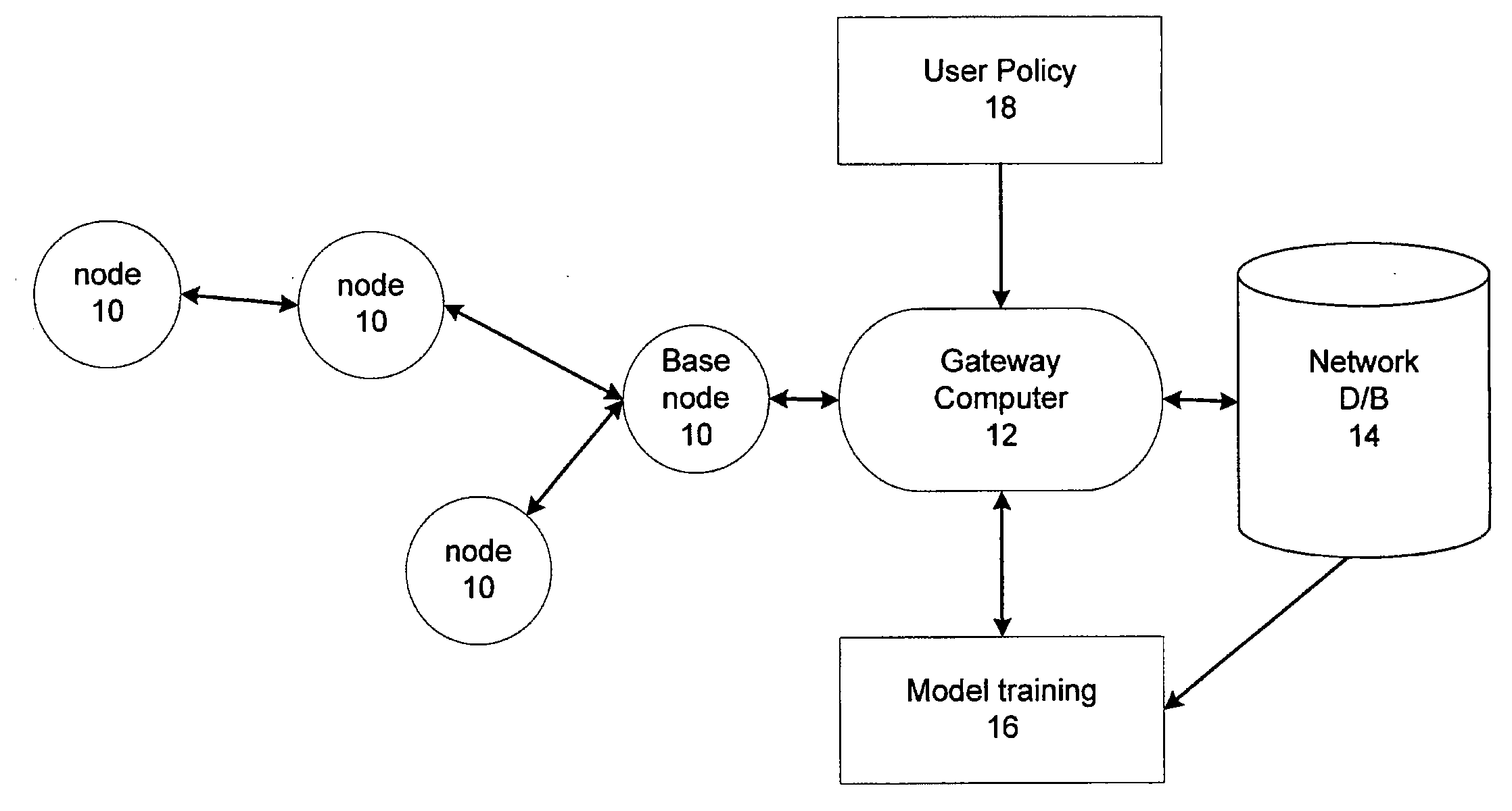
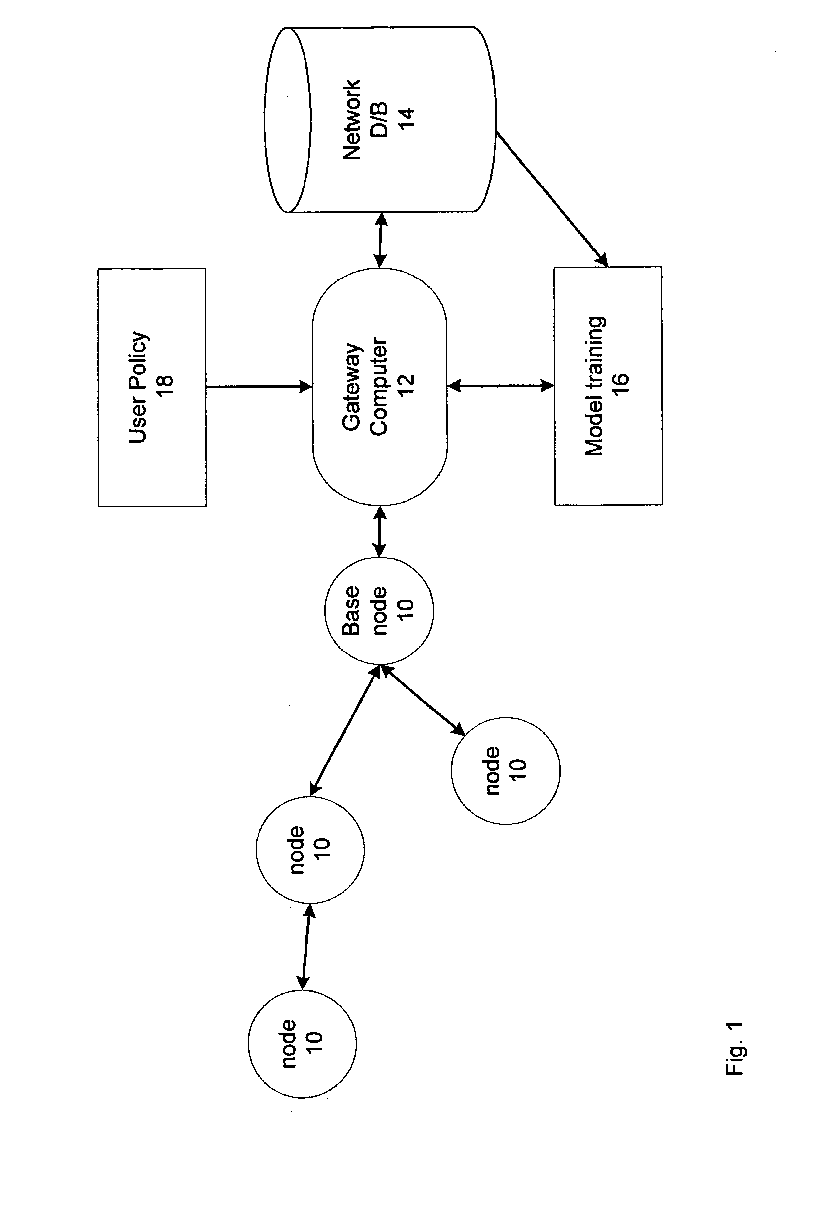
[0047]Referring first to FIG. 1 an array of multiple sensor nodes 10 are deployed to collect sensor data. The nodes 10 communicate in multi-hop fashion to deliver the data along a reporting path to a gateway computer 12 at the network hub. The data is subsequently stored in a historical record at a backend database 14 connected to the gateway computer 12.

[0048]Based on the historical data, an offline learning and training model 16 learns patterns in the historical data. The patterns are then used to identify the various physical phenomena that can occur in the current deployment, and these phenomena are each mapped to a finite set of sensor states. The training model 16 also learns the likelihood, of each sensor 10 being in each of their states.

[0049]A sensor network user then sets a desired application policy 18, which includes any one or more of at least the following:[0050]The network lifetime.[0051]The maximum and minimum sampling rates of each type of sensor.[0052]The possible ...


PUM


Abstract

This invention concerns remote sensor networks, and particularly energy management for wireless sensor networks. In a first aspect the invention is a wireless sensor node specified to operate for a given lifetime, comprising: an onboard computer system and a set of one or more associated sensors. The computer system operates to periodically sample data from each sensor of the set of associated sensors, and to store a multi-state model representing one or more phenomena described by the collected data. And, the computer system operates to calculate a value associated with movement of the phenomena between the states of the multi-state model, and to adjust the rate of sampling of one or more of the set of associated sensors depending on the calculated value. In other aspects the invention is a network of sensor nodes and a method of operation.

Description

TECHNICAL FIELD[0001]This invention concerns remote sensor networks, and particularly energy management for wireless sensor networks. In a first aspect the invention is a sensor node. In other aspects the invention is a network of sensor nodes and a method of operation.BACKGROUND ART[0002]In the relevant research literature, the thrust of energy management has been directed toward adjustment of the sampling frequency to conserve energy. For instance, U.S. Pat. No. 7,318,010 (Anderson) describes a node utilizing a fixed energy management plan which is downloaded to a sensor node and then used to adjust the sampling rates of the sensors reporting to that node. Although such protocols may enable nodes to last for a specified lifetime, they do not necessarily return the most useful range of information from the node during that lifetime.DISCLOSURE OF THE INVENTION[0003]In a first aspect the invention is a wireless sensor node specified to operate for a given lifetime, comprising an onbo...

Claims


Application Information

Patent Timeline
Patent Type & Authority Applications(United States)
IPC IPC(8): G06F17/18H04W4/38
CPCG01D15/00G01D1/00H04W4/38
Inventor WARK, TIMOTHYJURDAK, RAJA
Owner COMMONWEALTH SCI & IND RES ORG
Why Eureka
Try Eureka