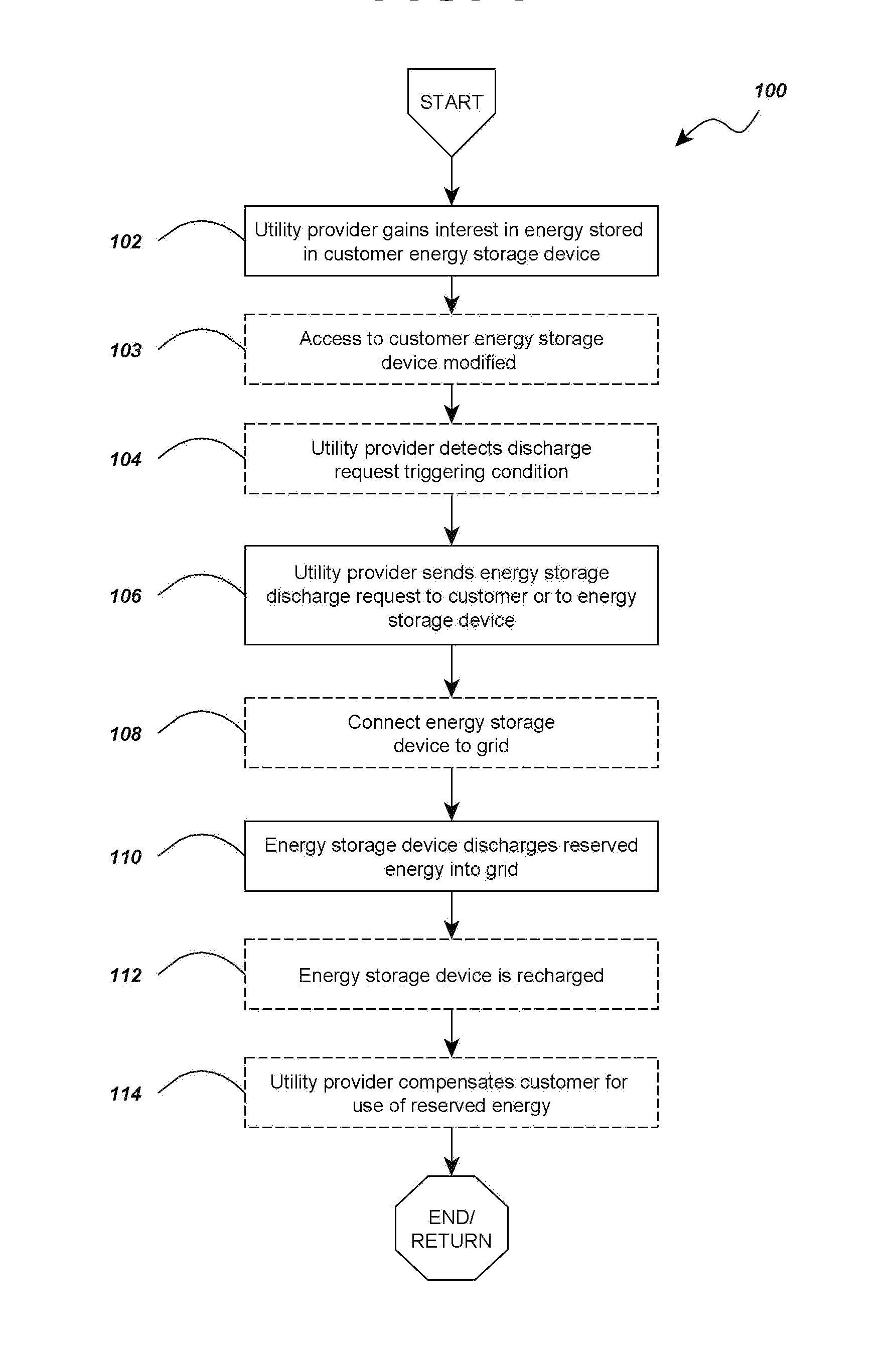
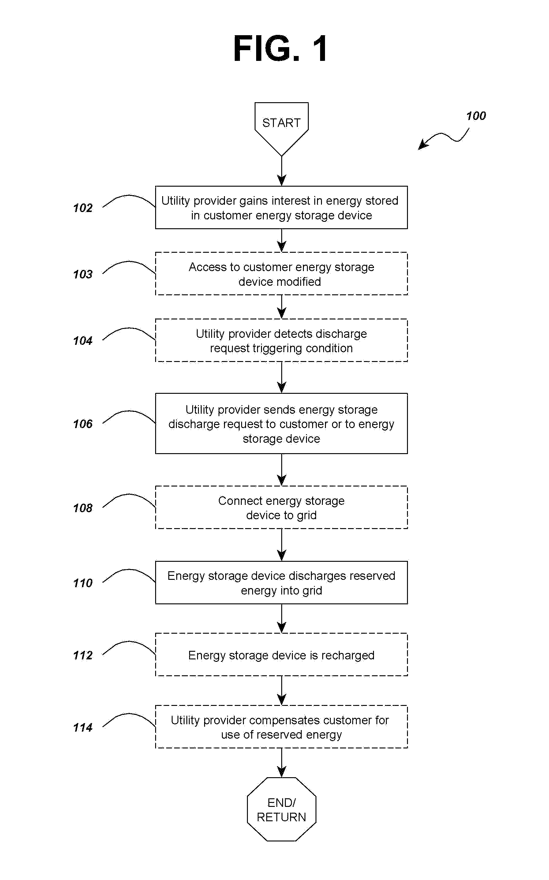
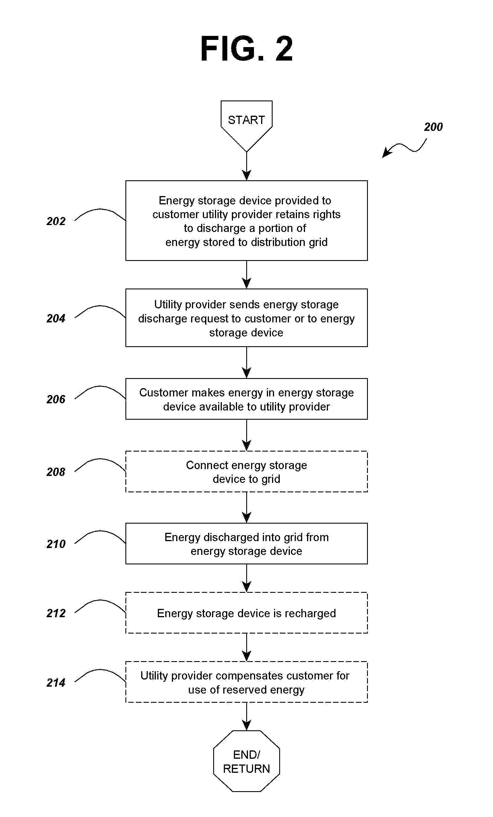
Energy allocation for energy storage cooperation

a technology for energy allocation and cooperation, applied in the direction of power network operation system integration, ac network load balancing, ac network voltage adjustment, etc., can solve the problems of difficult to track whether customers actually comply with their reduction obligations, difficult to determine the amount of reduction produced by each customer, etc., to reduce the total cost of ownership and other costs, increase efficiency, and reduce the effect of reliance on peaking power plants

Inactive Publication Date: 2012-09-27
ENGIE STORAGE SERVICES NA LLC
View PDF9 Cites 42 Cited by
  • Summary
  • Abstract
  • Description
  • Claims
  • Application Information

AI Technical Summary

Benefits of technology

[0006]In at least one aspect of the invention, some embodiments of the methods and apparatuses for allocating energy stored in energy storage devices disclosed herein may increase efficiency and reduce the total cost of ownership and other costs of the energy storage devices, power management systems, and backup power supplies deployed by customers by allocating the energy stored in these devices for the benefit of multiple parties, such as utility providers and customers. By allocating energy storage, utility providers such as electricity providers may benefit by having a ready source of supplemental energy reserved or on call for dispatch within their utility networks when demand response or other energy dispatch is needed, thereby reducing their reliance on peaking power plants, and customers may put energy to use that could otherwise be wasted.

Problems solved by technology

Peaking plants are an expensive source of power, so electricity providers pass on some of the costs of providing that power by billing a “demand charge” to certain types of customers based on the magnitude of their highest recorded energy consumption during a billing period.
However, it is often difficult to track whether customers actually comply with their reduction obligation, and determining the amount of reduction produced by each customer may be challenging.
In some cases, the backup power supplies are not frequently used and their energy storage capabilities end up wasted.
In other cases, utility providers and customers work together using energy storage devices to mitigate loads at the customers' sites so that the demand experienced by the surrounding grid is reduced, but the energy available to the utility providers for this purpose can be limited or reduced as the customer accesses the energy storage for its own purposes, and the energy may only be used to reduce demand at the site in which the storage device is located.

Method used


Image

  • Energy allocation for energy storage cooperation
  • Energy allocation for energy storage cooperation
  • Energy allocation for energy storage cooperation

Examples


Embodiment Construction

A. General Definitions and Information

[0040]Generally speaking, a utility provider in the embodiments herein may include a utility company such as an electricity producing or distributing company operating a utility distribution grid that transfers electrical energy from a generating means to customers for electricity consumption. The utility distribution grid may be comprised of various generation and transmission resources, such as, for example, power plants, feeders, substations, transformers, power lines, etc. In some embodiments a utility provider may be a water company managing a water distribution network (which may be referred to as a distribution grid) where water is directed and used in a process to produce electrical energy. A customer of the utility provider is an entity such as a person, household, structure, corporation, or business receiving or consuming energy directly from the utility distribution grid, but a customer may also be another utility provider which consu...


PUM


Abstract

Systems that allow energy allocation for energy storage cooperation are disclosed, with specific methods outlined concerning allocating energy stored by an energy storage device between a utility provider, a customer, and/or a third party. The methods may include allocating a portion of stored energy for a utility provider's benefit which may be gained as a result of a part of the allocated energy being dispatched into a utility network and allocating another portion of energy stored in the energy storage device for the benefit of the customer. Additional embodiments disclose the dispatching of the energy stored, signals used to bring about a dispatch, the nature of the relationship between the utility provider, the customer, and the energy stored, methods for making energy available to a utility provider without a prearranged reservation of the energy, penalties for misallocating energy, apparatus for allocating energy and causing dispatch, and more.

Description

CROSS-REFERENCE TO RELATED APPLICATIONS[0001]Priority is claimed to U.S. Provisional Patent Applications 61 / 467,908 and 61 / 467,929, both filed Mar. 25, 2011, which are hereby each incorporated by reference in their entirety.BACKGROUND[0002]The present invention relates to the field of electrical utility distribution and energy storage management and apparatuses and processes associated therewith.[0003]Today's electrical utility providers operate in a quickly-changing environment with limited resources and little room for error. Power demands placed on the utility grid may continuously and randomly fluctuate while the requirements necessary to satisfy these demands change on an hourly basis. Although hourly demands are somewhat predictable, utilities are expected to provide consistent and reliable power, regardless of what occurs in real time. Due to peaks in demand during the waking hours of 6 a.m. to 10 p.m., and during summer months, electricity providers contract with “peaking” p...

Claims


Application Information

Patent Timeline
Patent Type & Authority Applications(United States)
IPC IPC(8): H02J3/14
CPCH02J3/14Y02B70/3225H02J3/28Y04S20/224Y04S20/222H02J2310/60H02J3/144
Inventor GALATI, RICHARD C.
Owner ENGIE STORAGE SERVICES NA LLC
Why Eureka
Try Eureka