Brake drum

Active Publication Date: 2012-09-13
TEIKOKU PISTON RING CO LTD +1
View PDF7 Cites 2 Cited by
  • Summary
  • Abstract
  • Description
  • Claims
  • Application Information

AI Technical Summary

Benefits of technology

[0008]An object of the present invention is to provide a brake drum which can be improved in drag strength, strength and rigidity in the diametrical direction, joint strength, and heat radiating ability.
[0014]According to the brake drum of the present invention, the entire outer circumferential surface has a plurality of the projections, so the drag strength and heat radiating ability are improved. Further, the strength and rigidity in the diametrical direction are improved and abnormal noise is reduced. Further, by making part or all of the projections thin-waisted projections, the drag strength and joint strength are improved and greater thinness becomes possible.

Problems solved by technology

However, in the brake drum shown in Japanese Patent Publication (A) No. 2004-084889, fine relief shapes are formed at the outer circumferential surface, but shot blasting is used to form the relief shapes, so the drag strength in the rotational direction is not sufficient.
Further, the rigidity in the diametrical direction is not sufficient, so sometimes the vibration caused by friction with the brake shoe causes abnormal noise.

Method used


Image

  • Brake drum
  • Brake drum
  • Brake drum

Examples


Embodiment Construction

[0022]Below, preferred embodiments of the present invention will be explained while referring to the drawings.

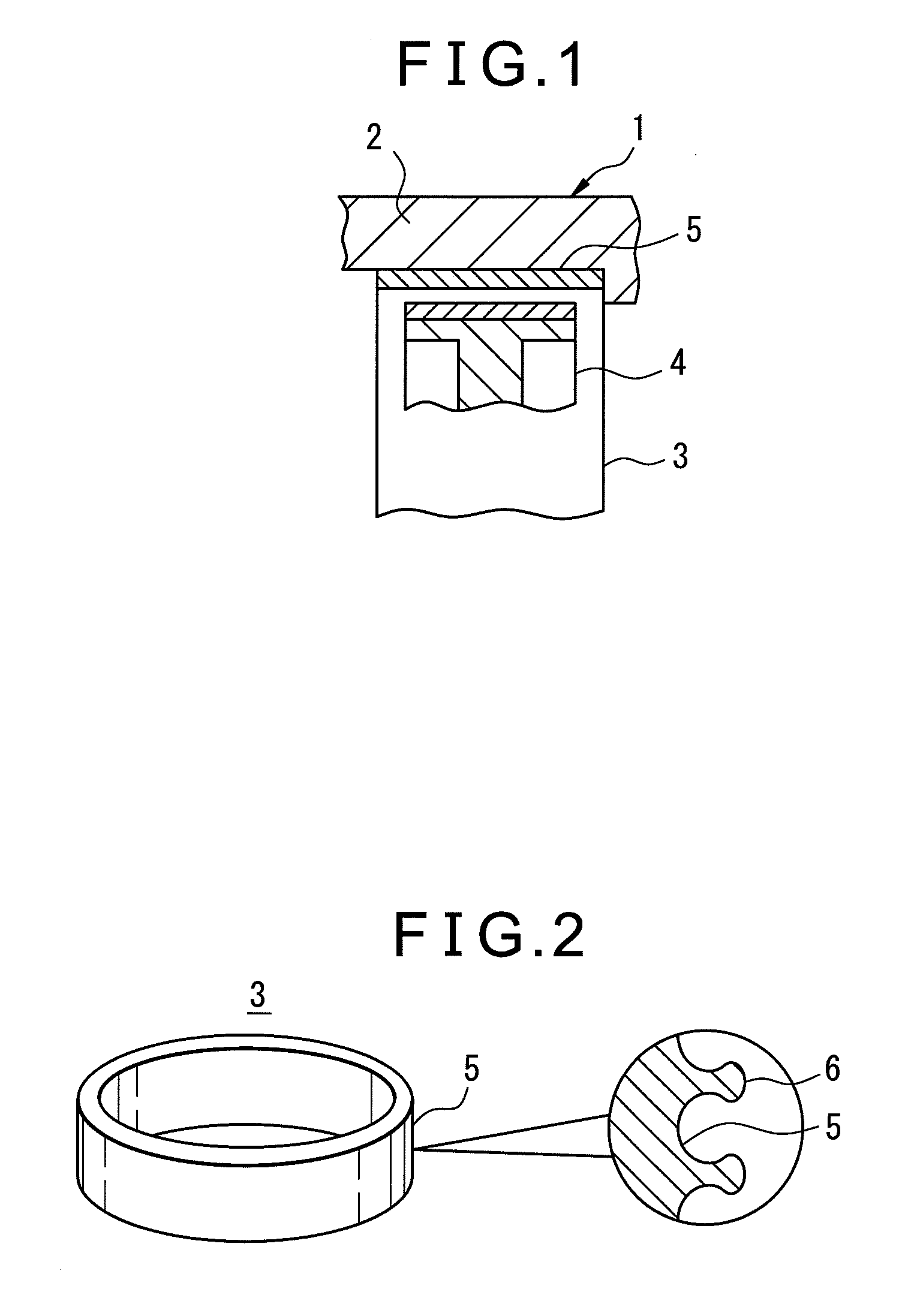
[0023]FIG. 1 shows a drum brake. At the inner circumferential surface of a cylindrically shaped drum part 2 of a wheel 1, a brake drum 3 is attached by insert casting. The wheel 1 is comprised of aluminum alloy or magnesium alloy, while the brake drum 3 is formed by cast iron, cast steel, or an aluminum alloy. Reference numeral 4 is a brake shoe having the action of being pressed against the inner circumference of the brake drum 3.

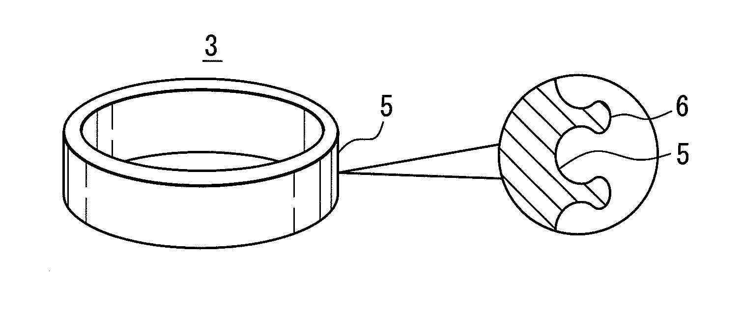
[0024]At the outer circumferential surface 5 of the cylindrically shaped brake drum 3 (see FIG. 2), a plurality of projections 6 are formed over the entire area. Among these projections 6, part or all of the projections 6 have thin-waisted shapes. The height of the projections 6 is 0.3 to 5.0 mm, while the number of the projections 6 is 5 to 100 / cm2.

[0025]If the height of the projections 6 is less than 0.3 mm, the drag strength in the rotational di...


PUM

PropertyMeasurementUnit
Heightaaaaaaaaaa

Abstract

A brake drum which can improve the drag strength, strength and rigidity in the diametrical direction, joint strength, and heat radiating ability, that is, a brake drum which is used for a drum brake, wherein the drum has a plurality of the projections at the outer circumferential surface, the plurality of the projections are formed at the outer circumferential surface as a whole when casting a brake drum, and at least part of the projections have thin-waisted shapes. A height of the projections is 0.3 to 5.0 mm, while the number of projections is 5 to 100 / cm2. The brake drum is produced by centrifugal casting.

Description

[0001]This application claims benefit of Serial No. 2011-048822, filed 7 Mar. 2011 in Japan and which application is incorporated herein by reference. To the extent appropriate, a claim of priority is made to the above disclosed application.BACKGROUND OF THE INVENTION[0002]1. Field of the Invention[0003]The present invention relates to a brake drum used for a drum brake of an automobile or motorcycle.[0004]2. Description of the Related Art[0005]As a brake drum, for example there is the one shown in Japanese Patent Publication (A) No. 2004-084889. Fine relief shapes are formed at the outer circumferential surface of the brake drum so as to increase the surface area and thereby improve the heat radiating ability and efficiently conduct heat generated at the brake drum from the fine relief shapes to a wheel hub.[0006]As related art, there is Japanese Patent Publication (A) No. 2004-084889.[0007]However, in the brake drum shown in Japanese Patent Publication (A) No. 2004-084889, fine re...

Claims


Application Information

Patent Timeline
IPC IPC(8): F16D65/10B22D13/00
CPCF16D65/10F16D65/827F16D2200/0004F16D2250/0007F16D2200/0021F16D2200/003F16D2200/0013
Inventor OZAWA, SHINGONOBE, TAKAHIRO
Owner TEIKOKU PISTON RING CO LTD
Why Eureka
Try Eureka