
Method and system for power delivery network analysis

a power delivery network and network analysis technology, applied in the field of printed circuit board design and analysis, can solve the problems of complex boundaries, prohibitive computational overhead of these algorithms, designer is often confronted with shapes and configurations far more complex,

Inactive Publication Date: 2012-08-30
CADENCE DESIGN SYST INC
View PDF19 Cites 21 Cited by
  • Summary
  • Abstract
  • Description
  • Claims
  • Application Information

AI Technical Summary

Benefits of technology

[0009]One or more of the following features may be included. In some embodiments, the three dimensional image is based upon, at least in part, at least one of time domain data and frequency domain data. In some embodiments, the three dimensional image is based upon, at least in part, at least one of voltage, current, temperature rise, current density, and impedance. In some embodiments, the three dimensional image is a three dimensional animation. In some embodiments, the three dimensional image includes a worst case function. In some embodiments, the three dimensional image includes a cross probe function. The method may further include providing an editable user interface having one or more editable fields, the editable fields including at least one of voltage, impedance, voltage IRDrop, current, density, and temperature rise. The method may also include importing a background file. The method may additionally include generating a stack-up informational display.
[0010]In another embodiment of the present disclosure, a computer program product residing on a computer readable storage medium having a plurality of instructions stored thereon is provided. The instructions, when executed by a processor, cause the processor to perform operations. Some operations may include extracting, using at least one processor, an electromagnetic (EM) model for each of one or more discontinuity structures associated with an electronic circuit design. Operations may further include performing a power delivery network analysis of the electronic circuit design, the PDN analysis including a Method of Moments (MoM) calculation. Operations may also include displaying a three dimensional image depicting one or more results of the PDN analysis.
[0011]One or more of the following features may be included. In some embodiments, the three dimensional image is based upon, at least in part, at least one of time domain data and frequency domain data. In some embodiments, the three dimensional image is based upon, at least in part, at least one of voltage, current, temperature rise, current density, and impedance. In some embodiments, the three dimensional image is a three dimensional animation. In some embodiments, the three dimensional image includes a worst case function. In some embodiments, the three dimensional image includes a cross probe function. Operations may further include providing an editable user interface having one or more editable fields, the editable fie...

Problems solved by technology

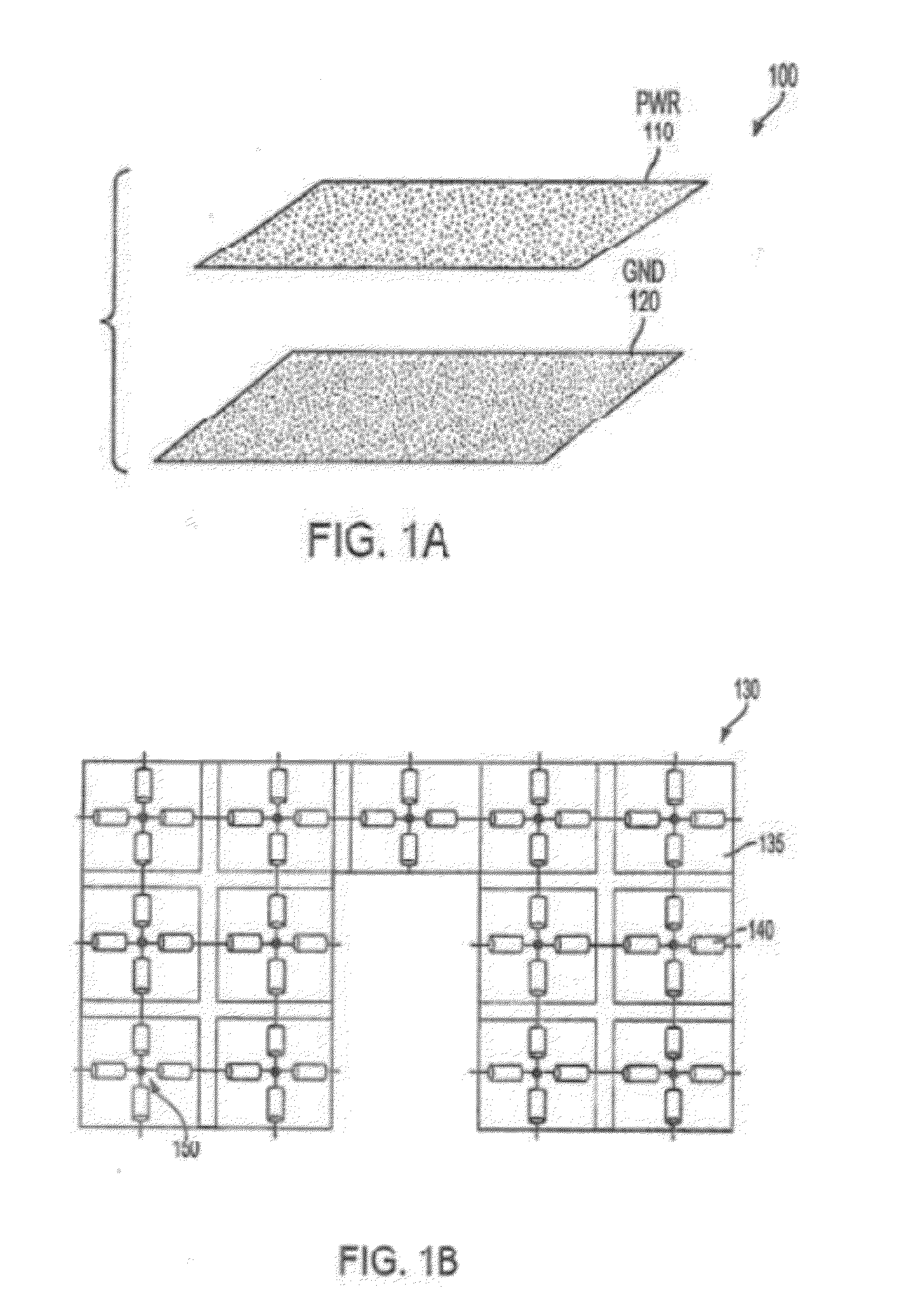
Whereas, it is not difficult to model a simple plane pair transmission line, the abstract shapes of typical PGPPs result in complex boundaries some of which may be internal to the exterior boundary of the PGPP.
While several algorithms can be used to model the complex shapes of a PGPP, the computational overhead for these algorithms are prohibitive, especially where such PI analysis tools must share computational resources with other design tools.
Unfortunately, the designer is often confronted with shapes and configuration far more complex than the simple PGPP shown in FIG. 1A.
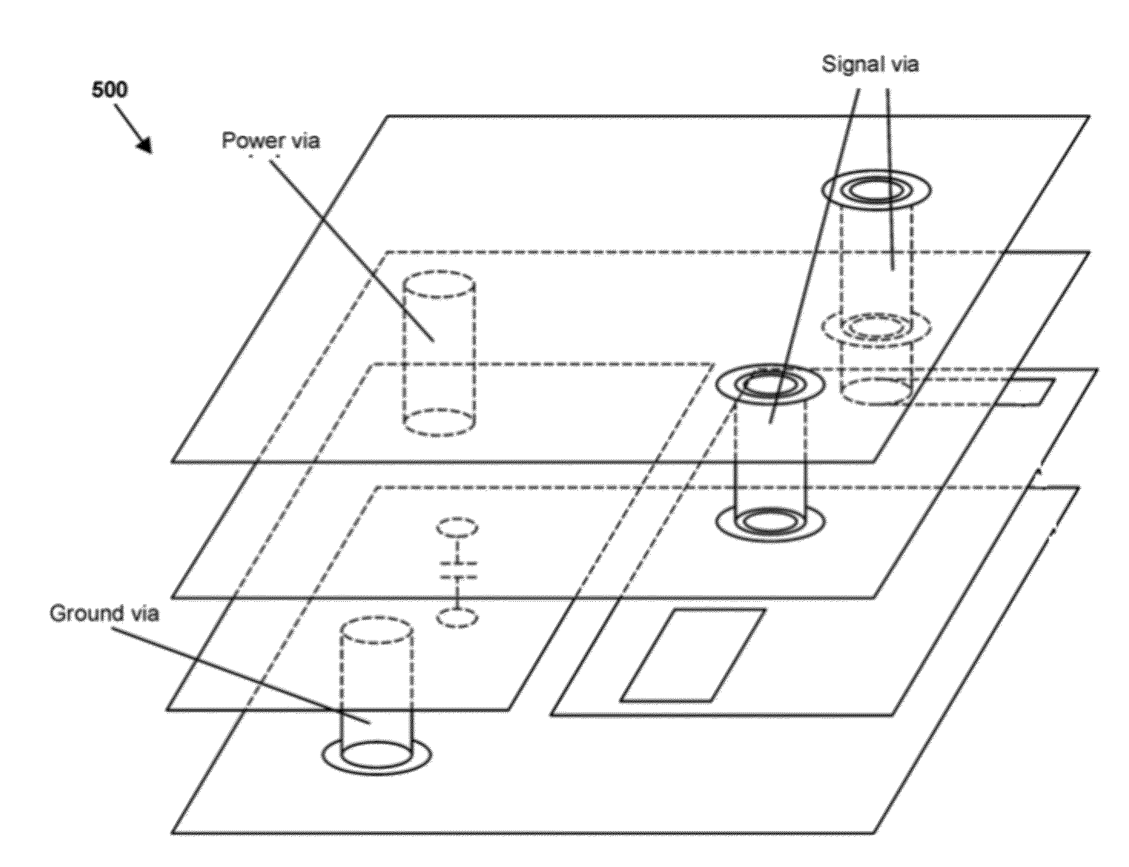
For example, splits, voids, cutouts as well as stitched power, ground and signal vias provide additional problems for the designer of a particular circuit.

Method used


Image

  • Method and system for power delivery network analysis
  • Method and system for power delivery network analysis
  • Method and system for power delivery network analysis

Examples


Embodiment Construction

[0071]Reference will now be made in detail to the embodiments of the present disclosure, examples of which are illustrated in the accompanying drawings. The present disclosure may, however, be embodied in many different forms and should not be construed as being limited to the embodiments set forth herein. Rather, these embodiments are provided so that this disclosure will be thorough and complete, and will fully convey the concept of the disclosure to those skilled in the art.

[0072]As will be appreciated by one skilled in the art, the present disclosure may be embodied as a method, system, or computer program product. Accordingly, the present disclosure may take the form of an entirely hardware embodiment, an entirely software embodiment (including firmware, resident software, micro-code, etc.) or an embodiment combining software and hardware aspects that may all generally be referred to herein as a “circuit,”“module” or “system.” Furthermore, the present disclosure may take the fo...


PUM


Abstract

The subject application relates to a method and system for power delivery network analysis. The present disclosure is directed towards a computer-implemented method for displaying one or more results of a power delivery network (PDN) analysis associated with an electronic circuit design. The method may include extracting, using at least one processor, an electromagnetic (EM) model for each of one or more discontinuity structures associated with the electronic circuit design. The method may further include performing a power delivery network analysis of the electronic circuit design, the PDN analysis including a Method of Moments (MoM) calculation. The method may also include displaying a three dimensional image depicting one or more results of the PDN analysis. Numerous other features are also within the scope of the present disclosure.

Description

RELATED APPLICATIONS[0001]The subject application claims the priority of the following Chinese Applications: Chinese Application No. 201110049844.1, filed on Feb. 24, 2011, Chinese Application No. 201110048078.7, filed on Feb. 24, 2011, and Chinese Application No. 201110048087.6, filed on Feb. 24, 2011, the contents of which are herein incorporated by reference in their entirety.FIELD OF THE INVENTION[0002]The present disclosure relates to printed circuit board (PCB) design and analysis. More specifically, the present disclosure relates to power delivery network (PDN) analysis, which may occur prior to fabrication of an actual integrated circuit (IC).DISCUSSION OF THE RELATED ART[0003]PDN analysis including power integrity (PI) and IRDrop has become a focus of circuit designers. These tools allow the power distribution network to be simulated and modified in both the design and verification phases. When the PDN analysis is executed, a frequency response of the PDN may be analyzed. D...

Claims


Application Information

Patent Timeline
IPC IPC(8): G06F17/50
CPCG06F17/5045G06F17/509G06F17/5036G06F17/5018G06F2217/78G06F30/18G06F30/30G06F2119/06G06F30/367G06F30/23G06F30/398G06F2113/04
Inventor DAI, WENLIANGCHEN, LANBINGFENG, GUOYINGLIU, PINGNAGLE, DENNISTAN, JILINZHANG, WENJIANZHAO, QIZHOU, ZHONGYONG
Owner CADENCE DESIGN SYST INC
Learn More