
Integrated solar energy system

a solar energy system and integrated technology, applied in the direction of heat collector mounting/support, hybrid energy generation, thermal-pv hybrid energy generation, etc., can solve the problem that solar generated energy continues to provide only a very small portion of the energy requirements, and achieve the effect of high energy outpu

Inactive Publication Date: 2012-08-30
ROUNTREE JOHN
View PDF6 Cites 5 Cited by
  • Summary
  • Abstract
  • Description
  • Claims
  • Application Information

AI Technical Summary

Benefits of technology

[0008]It is therefore an object of the present disclosure to provide solar energy equipment with a high energy output.
[0009]It is therefore a further object of the present disclosure to provide solar energy equipment which is reliable and requires minimal maintenance.
[0010]It is therefore a still further object of the present disclosure to provide solar energy equipment which is readily and easily installed on a wide range of architectural structures.
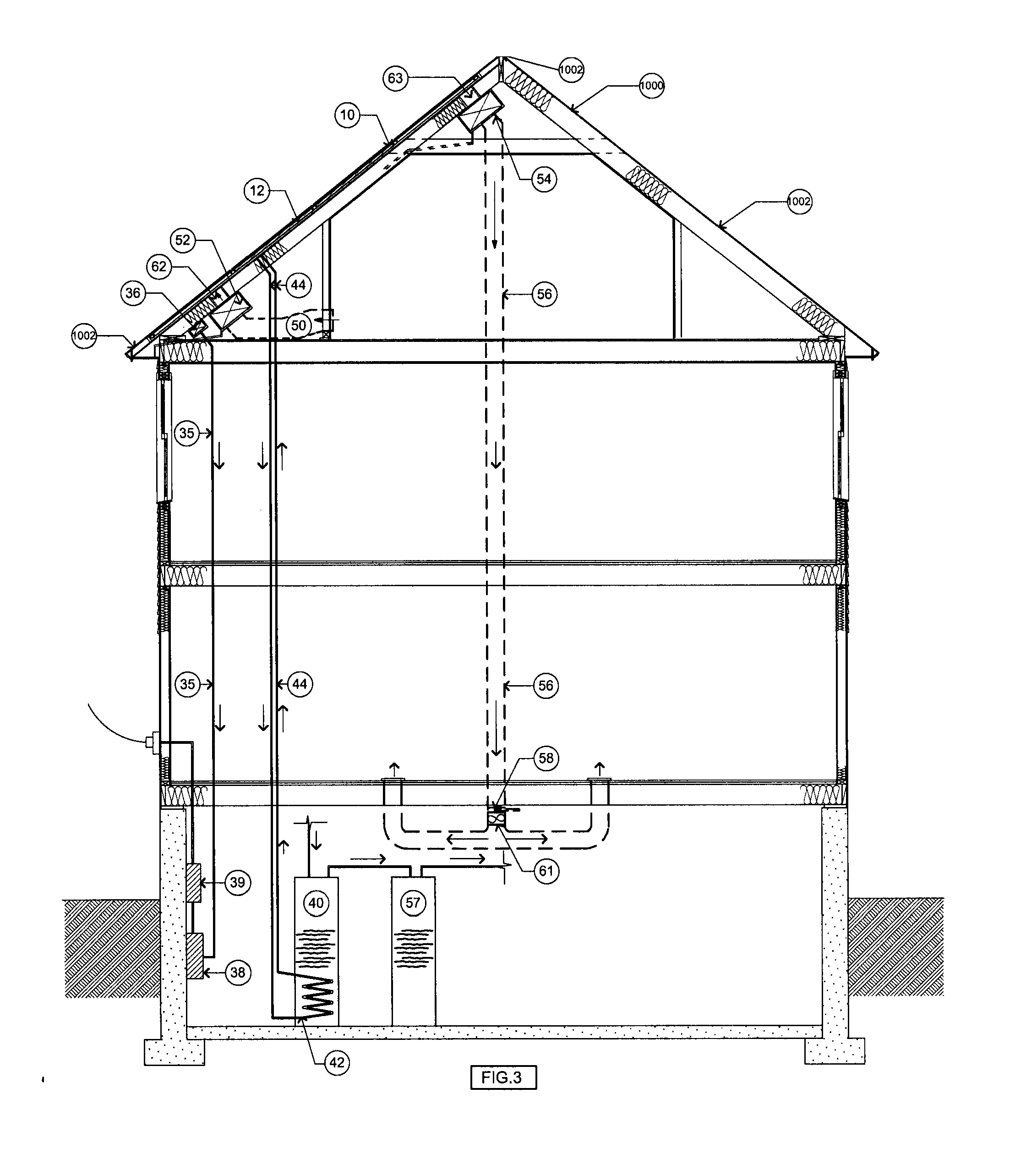
[0011]These and other advantages are obtained by providing a building-integrated solar system which provides solar generated electricity, provides solar generated hot water and which has a heat recovery ventilation system which can provide solar heated air in the winter as well as cooled air to the photovoltaic panels in the summer. The system further provides a durable long lasting roof membrane.
[0012]Further, the system typically integrates these four functions into one product while providing an architecturally pleasing, flush mounted appearance. It is expected that the combination and synergy of multiple solar strategies will typically increase the overall efficiency of the system and consequently, the economic investment return.
[0014]The system will typically be provided in the form of a combination of photovoltaic panels and solar domestic hot water heating panels, and will typically be designed to be modular and adaptable to a variety of roof shapes. The system will typically utilize commercial skylight and curtain wall technology. The panels are typically mounted to a concealed aluminum frame. Further, the system will typically have a continuous air space below the panels to allow air circulation. The panels typically will be flashed into a roof that is built-up around the perimeter of the system so that the roof and panels are flush with each other. Alternatively, the entire roof surface can be designed using the present system thereby creating an aesthetic appearance.

Problems solved by technology

However, in spite of the nearly universal popular support for such energy, solar generated energy continues to provide only a very small portion of the energy requirements, either nationally or internationally.

Method used


Image

  • Integrated solar energy system
  • Integrated solar energy system
  • Integrated solar energy system

Examples


Embodiment Construction

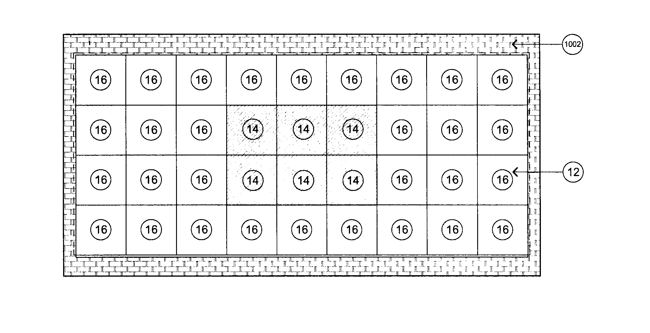
[0031]Referring now to the drawings in detail wherein like numerals indicate like elements throughout the several views, one sees that FIG. 1 is an elevation view of an exterior of the system 10 of the present disclosure while FIG. 2 is an elevation view of the system 10 mounted on a house 1000 which can, of course, be virtually any architectural structure, and is not limited thereby. Typically, the system 10 is mounted on roof 1002 of house 1000. Solar array 12 is shown as a nine by four array or matrix formed from centrally located solar thermal collector panels 14 (adjacent to each other) surrounded by photovoltaic panels 16 (adjacent to each other) around the perimeter. Of course, other sizes of arrays could be used for different applications, with different numbers of panels, depending upon the underlying architectural constraints and the amount of energy required from the system. Solar thermal collector panels 14 are configured for solar domestic hot water, while photovoltaic ...


PUM


Abstract

The system is an integrated solar energy system which provides solar generated electricity by photovoltaic panels, provides solar generated hot water by solar collector thermal panels and which has a heat recovery ventilation system which can provide heated or cooled air. The system further provides a durable long lasting roof membrane.

Description

BACKGROUND OF THE DISCLOSURE[0001]1. Field of the Disclosure[0002]The present disclosure relates to an integrated solar energy system which includes photovoltaic cells which provide solar generated electricity, solar thermal collector panels which provide solar generated hot water and a heat recovery ventilation system which can through a cooling effect, improve the performance of the photovoltaic modules year-round and provide useful heated air to a building during the heating season.[0003]2. Description of the Prior Art[0004]The utility and desirability of solar generated energy have been well-established on economic, political and environmental grounds. However, in spite of the nearly universal popular support for such energy, solar generated energy continues to provide only a very small portion of the energy requirements, either nationally or internationally.[0005]The capture of the solar energy and the subsequent conversion into useful energy can take many forms. Firstly, photo...

Claims


Application Information

Patent Timeline
IPC IPC(8): H01L31/058F24J2/30F24J2/04F24S10/30
CPCY02B10/20Y02B10/12Y02B10/70Y02E10/60H02S40/44F24J2/5209Y02E10/44Y02E10/47H02S20/25F24J2/045F24S20/67F24S25/37Y02B10/10Y02E10/50
Inventor ROUNTREE, JOHN
Owner ROUNTREE JOHN
Learn More