Eureka AIR delivers breakthrough ideas for toughest innovation challenges, trusted by R&D personnel around the world.

Vertical axis omni-directional wind turbine

a wind turbine and vertical axis technology, applied in machines/engines, renewable energy generation, greenhouse gas reduction, etc., can solve the problems of falling into comparative disuse, unable to enjoy the benefits of transmission and generators, and what is suitable for keeping a small water tank full or cattle is ordinarily not enough to power a modern hous

Inactive Publication Date: 2008-11-06
WEPOWER
View PDF4 Cites 23 Cited by
  • Summary
  • Abstract
  • Description
  • Claims
  • Application Information

AI Technical Summary

Benefits of technology

[0013]According to a preferred but optional feature of this invention, the vane is so configured that when coupled to the generator, it will exhibit a substantially linear energy output that is limited by system parameters such as generator counter-EMF, bearing loads, and aerodynamic cleanliness of the vanes. The rotor will not run away. Importantly, when an abrupt acceleration by way of a substantial burst of wind occurs near the terminal velocity at lower speeds, this turbine abruptly speeds up and persists at a higher rotary velocity while the higher wind speed prevails, this provides a higher energy output under conditions when it is most needed, such as in cold and wind storms. Speeds in this condition are also terminally limited relative to the existing parallel.

Problems solved by technology

As a source of modest amounts of energy for very localized usage, it has a well-deserved reputation, but it has fallen into comparative disuse as electrical power grids have been established, and as power requirements have increased beyond the capacity of such small devices.
What is suitable for keeping a small water tank full or cattle is ordinarily not sufficient to power a modern house.
Smaller installations cannot enjoy the benefits of long blades and of transmissions and generators which require substantial housings, all atop a very high and robust tower.
Among the very practical limitations of the modern horizontal turbine is the height of the tower required for ground clearance of the large propellers.
These conditions are profound limits when one considers providing electrical energy for installations such as homes and small shops where ground clearances are of critical importance.

Method used


Image

  • Vertical axis omni-directional wind turbine
  • Vertical axis omni-directional wind turbine
  • Vertical axis omni-directional wind turbine

Examples


Embodiment Construction

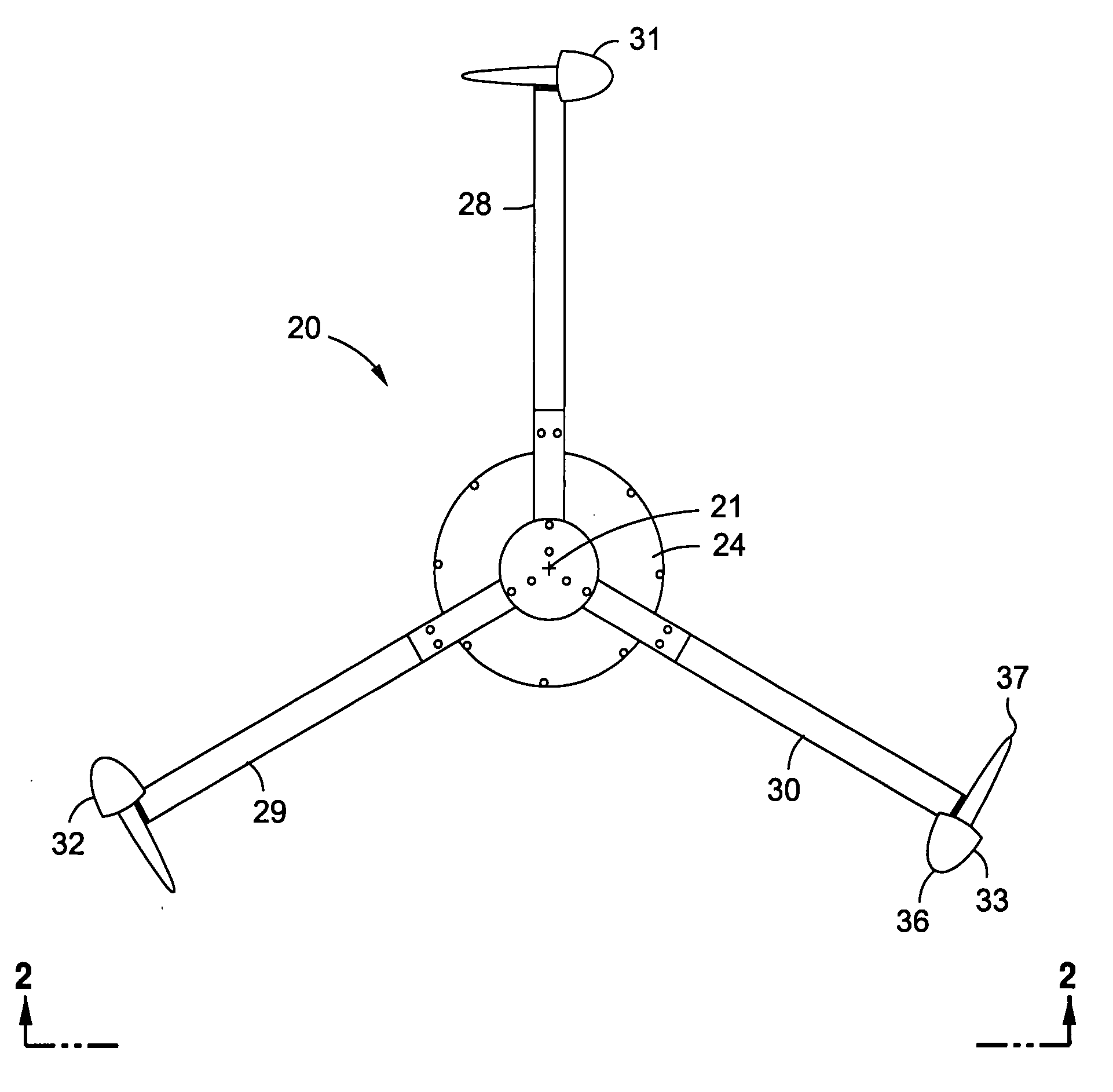
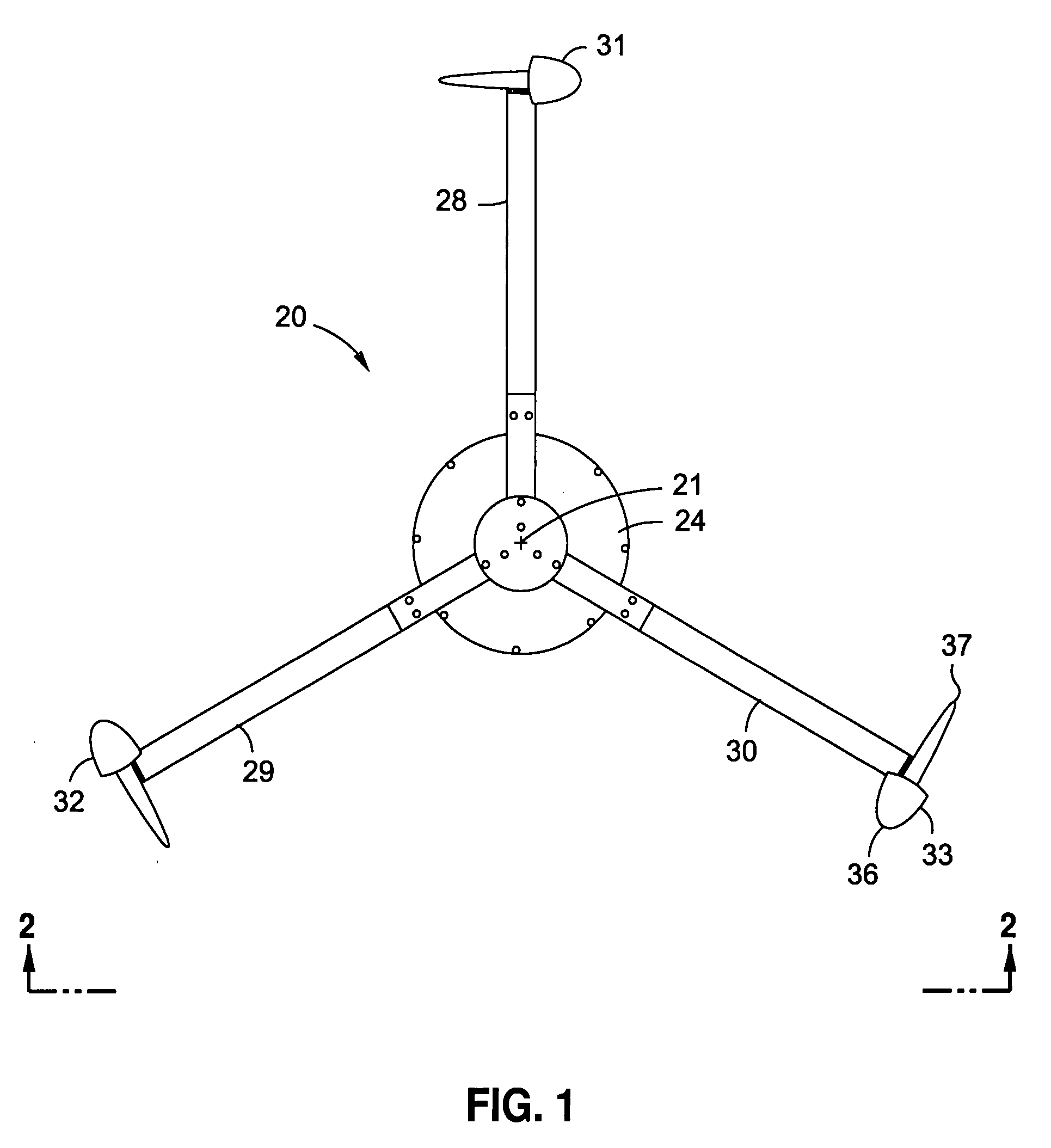
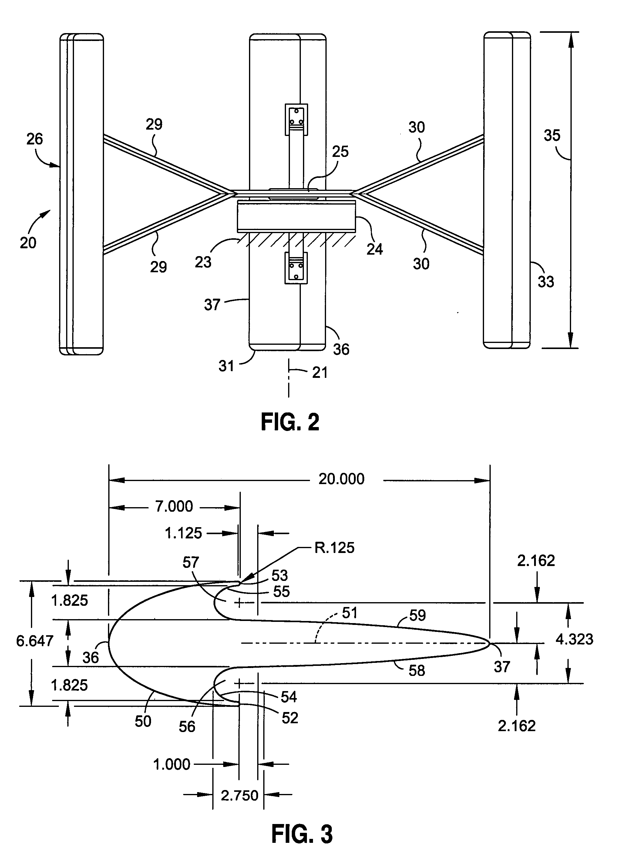
[0019]FIGS. 1 and 2 show a wind turbine 20 with a central axis of rotation 21 intended to stand vertically. As an example of its simplest and preferred structure, it is supported on a base 23 to which generator 24 is mounted. A bearing 25 supports rotor 26 and is directly connected to the rotor of the schematically-shown electrical generator so rotation of the rotor 26 drives the generator. Bearing 25 mounts two sets of three arms 28, 29, 30 each, one set above the other.

[0020]Vanes 31, 32, 33 are rigidly fixed to the ends of respective arms 28, 29, 30. While a rotor with only two vanes will function, it is subject to undesirable vibrations at some speeds. An odd number of vanes is to be preferred, and is illustrated. Use of odd numbers of vanes improves the starting reliability of the turbine at slower wind speeds.

[0021]The vanes are all identical. Each has a dimension 35 of height, a leading edge 36, and a trailing edge 37. In FIG. 1 the same vane is portrayed in three orientation...


PUM

PropertyMeasurementUnit
diameteraaaaaaaaaa
heightaaaaaaaaaa
speed accelerationaaaaaaaaaa

Abstract

A vertical axis wind turbine with a rotor driven by a group of vanes that assure starting at low speeds, efficiently generates electricity at all wind speeds, especially under circumstances that include abrupt increases in the wind velocity.

Description

FIELD OF THE INVENTION[0001]Vertical axis omni-directional axis wind turbines with enhanced efficiency of wind stream energy and reliability of starting from rest.BACKGROUND OF THE INVENTION[0002]Wind driven turbines are generally divided into two classes on the basis of the orientation of their axis of rotation. The preponderance of major wind turbine installations have their axis horizontal, facing into the wind, often with propeller type blades. These are frequently seen in large “farms” in canyon passes and on mountainsides.[0003]Horizontal axis turbines require substantial trunnions and related mechanisms to face the turbine into the wind. The simple Aeromotor windmill is a classical example. It has a tail fin that exerts a torque to center the axis into the wind. These have decorated the farming landscape for decades, especially for pumping water from wells. As a source of modest amounts of energy for very localized usage, it has a well-deserved reputation, but it has fallen i...

Claims


Application Information

Patent Timeline
Patent Type & Authority Applications(United States)
IPC IPC(8): F03D3/06
CPCF03D3/061F05B2240/301Y10T29/49316Y02B10/70Y02E10/74Y02B10/30
Inventor WATKINS, PHILIP G.
Owner WEPOWER
Why Eureka
Eureka Blog
Learn More